Working with Mission Vignette and Scenario diagram
The Mission Vignette and Scenario diagram (Mi-Pm-VS) shows the elements and relationships that are involved in defining the environments and conditions applicable to capability, operational concept, or set of systems.
The Mission Vignette and Scenario diagram can be created under the Parameter package of each domain (e.g, Operational Parameters, Strategic Parameters)
Creating a diagram
An example is shown with the Strategic Parameters, but the Mission Vignette and Scenario diagram can be created under other domain Parameters packages also.
To create a Mission Vignette and Scenario diagram
- In the Containment Tree, select the Strategic Parameters and do one of the following:
- From the selected package's shortcut menu, select Create Diagram > Mission Vignette and Scenario.
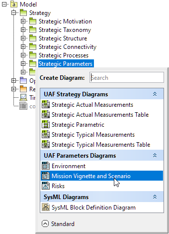
- In the modeling tool's main menu, click Create Diagram, search for Mission Vignette and Scenario, and select it.
- From the selected package's shortcut menu, select Create Diagram > Mission Vignette and Scenario.
- Name a diagram or leave it with the default name.
Creating an element
When the diagram is created, you can start creating the appropriate elements. An example is described using the Mission Scenario element, but the same is valid for other elements.
To create a Mission Scenario in a diagram
- In the diagram palette, click the Mission Scenario and then click the appropriate place on the diagram pane.
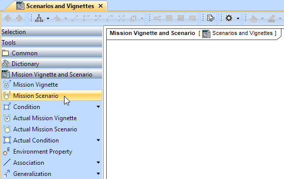
- Name the element.
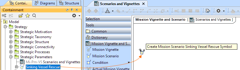
To create a Mission Scenario in a Containment tree
- In the Containment tree, right-click the Strategic Parameters package and from the shortcut menu, select Create Element. Search for the Mission Scenario and select it.
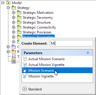
- Name the element.
- Drag the created element from the Containment tree to the diagram pane.
To create the elements from other resources (e.g. Word, Excel, HTML)
- Copy a list in your resource.
- In a diagram, press Ctrl+V and from the Paste Special dialog, choose Element.
- From the Select Type dialog, choose Mission Scenario (or other appropriate element).
For more information about creating the elements from other resources, see (2026x Refresh1) Creating elements from other resources.
Connect the Mission Scenario
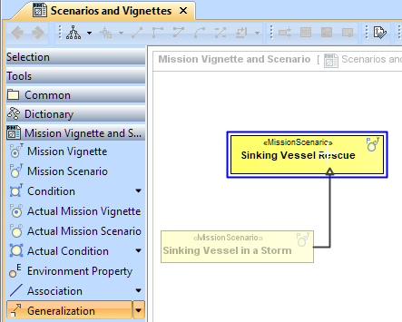
When you have the Mission Scenario elements created, you can start connecting them using the Generalization relationship.
To connect the elements with the Generalization relationship
- Select an element from which the Generalization will be drawn.
From the smart manipulator, which appears after you select the element, choose Generalization.

You can also select the Generalization relationship from the diagram palette.
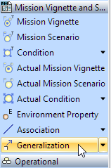
- Move the mouse pointer over the target element and click to finish the action.
If there is a need, you can make the Generalization target element abstract.
To make an element abstract
- Select an element and open its (2026x Refresh1) Specification window.
- Make sure that All is chosen for Properties.
- Search for Is Abstract and set it to true.
To view the inherited properties
- Select an element and open its (2026x Refresh1) Specification window.
- Click Attributes, Properties, or Relations property group.