SysML v2 Plugin
Released on: June 26, 2026
The SysML v2 Plugin 2026x Refresh1 release introduces model validation with customizable validation suites and rules, helping ensure the accuracy, completeness, and consistency of models through automated validation across views and the Textual Editor.
The release expands tabular view capabilities with hierarchical display modes, non-persistent tables, enhanced column and row management, and improved cell editing. Symbolic views have been enhanced with additional visualization capabilities, including support for displaying traceability patterns such as satisfy, verify, perform, include, and others as paths, along with note support, representation control for templated buttons in custom symbolic view palettes, and improved display of port and parameter information.
Style sheet functionality has been significantly expanded, enabling style sheet creation, application, extraction, and management directly in symbolic views, as well as rule specification through the Specification panel.
The release also introduces model-based customization of Element Creation and Relationship Creation dialogs, providing greater control over project-specific modeling workflows.
The Textual Editor delivers substantial performance improvements, enhanced navigation, multiple-file import support, in-editor task notifications, and new environment options.
The Specification panel has been expanded with an in-line value editor for compartment elements, color selection, element direction management, and other usability enhancements. The Specification Window now also includes search functionality.
Additional highlights include enhancements to the SysML v1 to SysML v2 Migration Plugin with broader model and diagram coverage, and the introduction of the SysML v2 Open API technology preview.
To download the latest version of the modeling tool, see Downloading installation files.
SysML v2 Features
Model Validation
This release introduces model validation, which helps ensure the accuracy, completeness, and consistency of your models. The modeling tool checks elements against validation rules delivered through SysML, KerML, and Dassault Systèmes predefined validation rules. By automatically identifying modeling issues, validation helps maintain model quality and supports compliance with modeling standards. Learn more >>
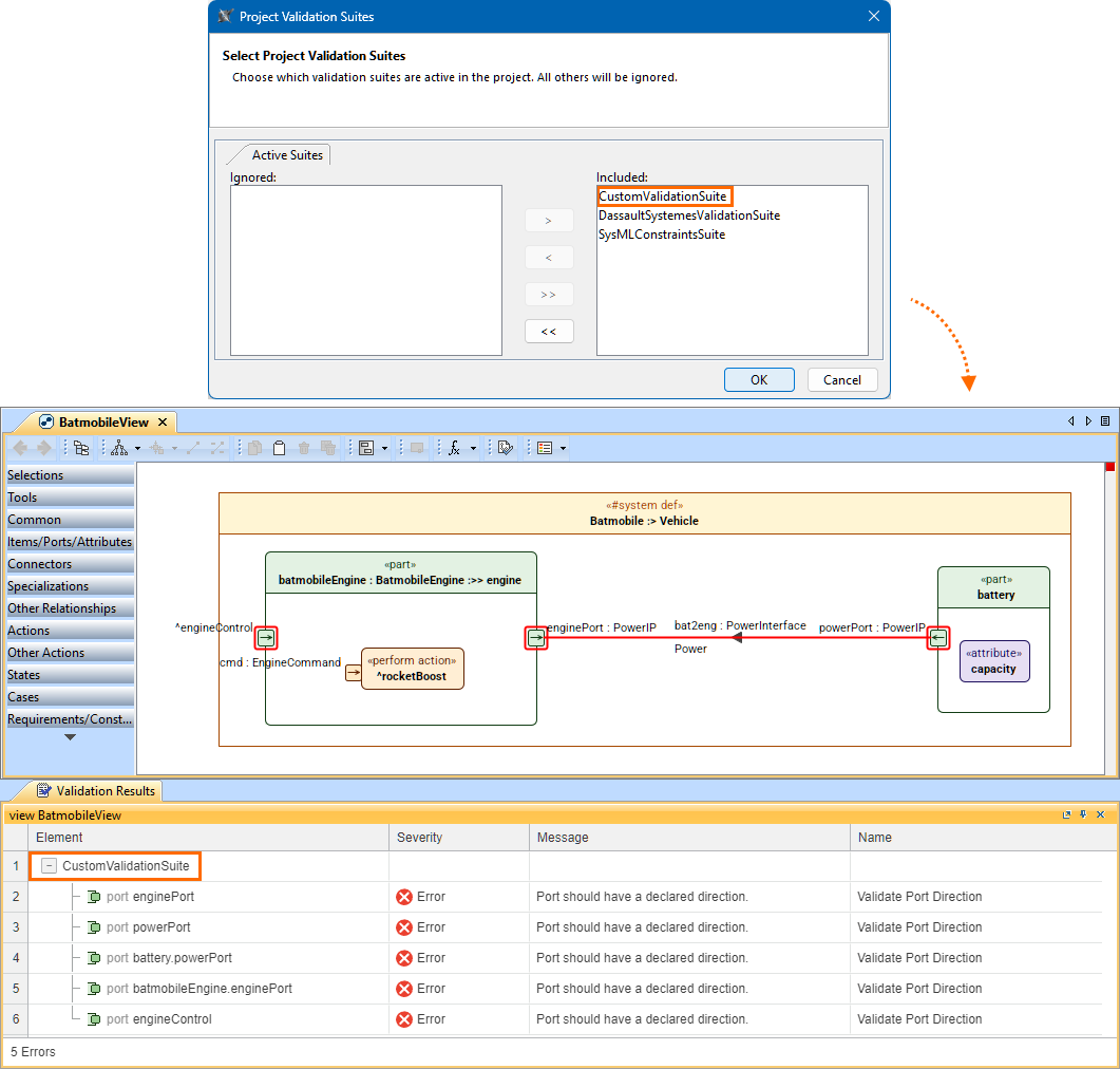
Validating Elements in Views
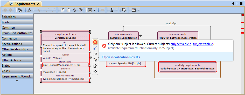
- Failing elements are highlighted in views, enabling immediate identification of failures directly in the view. You can also invoke the Validation Results pop-up via the Show Validation Results button in the failing element's smart manipulator. The pop-up displays the element's validation results and provides details explaining the failure, helping you quickly understand the issue. Learn more >>
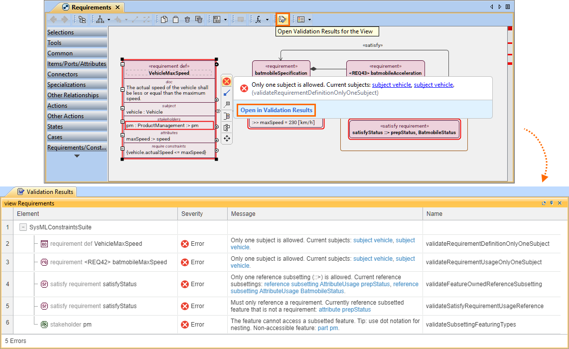
- Additionally, you can review the validation results for all failed elements displayed in the view by opening the Validation Results panel. You can access it either from the Validation Results pop-up or via the Open Validation Results for the View button. This provides a consolidated overview of issues within the current view, improving efficiency when addressing multiple validation failures. Learn more >>
Validating Elements in Textual Editor
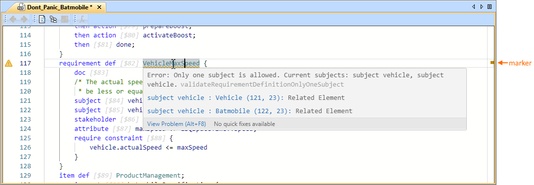
Textual notation is validated directly in the Textual Editor when the Run Validation option is enabled (default). The opened namespace is validated automatically, and failing elements are underlined. Hovering over an underlined element displays a Validation Results pop-up with details about the failure. The editor scroll bar also includes markers indicating failure locations, with colors reflecting severity. This enables you to identify and review issues immediately within the Textual Editor, improving efficiency and reducing the need to switch between views. Learn more >>
Validating Elements
You can validate individual elements with their recursive contents using the Validate command. The command is available in the element shortcut menu, accessible from both the Containment tree and the element symbol in a view. The command validates the selected element and all elements contained within it, then opens the Validation Results panel for review. This enables efficient validation of entire model structures in a single action. Learn more >>

Custom Validation Suites and Rules
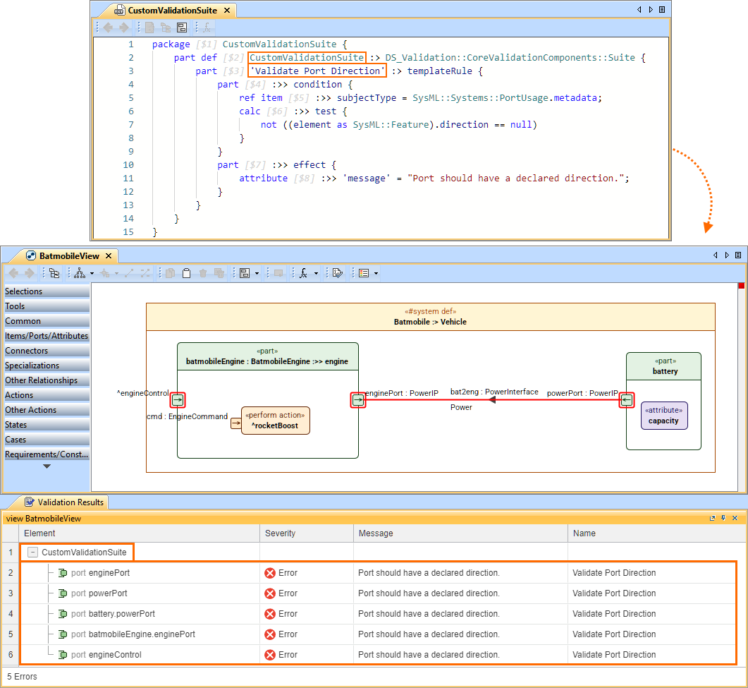
Instead of, or in addition to the predefined validation suites, you can create your own validation suites with custom validation rules. This allows you to tailor model validation to your project-specific modeling standards. Learn more >>
Validation Suites Management
Additionally, you can enable or disable validation suites for your project through the Project Validation Suites dialog. The predefined validation suites are enabled by default for all SysML v2 projects, but you can easily disable them and/or activate other suites as needed to match your project needs. Learn more >>
Tabular Views Improvements
Element Display Modes for Tables
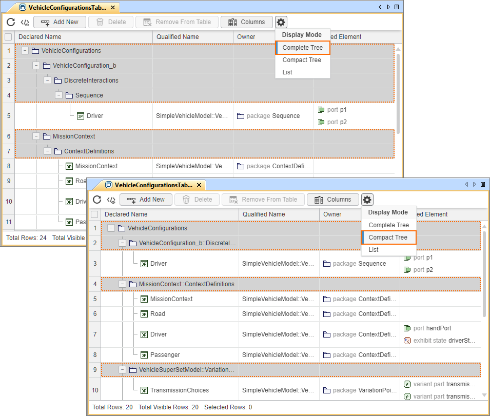
You can now view tables in a hierarchical (tree) structure, where rows are organized by ownership. Specify the display mode via the Options button in the table toolbar or by redefining the dedicated attributes via the Textual Editor. Two hierarchical display modes are available:
Learn more >>
- Complete tree displays the row elements in a hierarchy where all element owners are represented in separate rows.
- Compact tree displays the row elements in a hierarchy where common element owners are grouped in a single row.
Open in Table Command
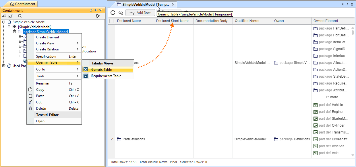
The newly introduced Open in Table command allows you to view the selected element's content in any tabular view available in the active View Creation dialog without creating a tabular view in the model. This functionality can be useful when you want to quickly review parts of the model in a tabular view without impacting the model. Learn more >>
Column Configuration Interface
- A new user interface has been introduced to manage table columns. The table toolbar now includes the Columns button, whose dropdown menu displays all existing columns, allowing you to select or deselect them to show or hide table columns. Learn more >>
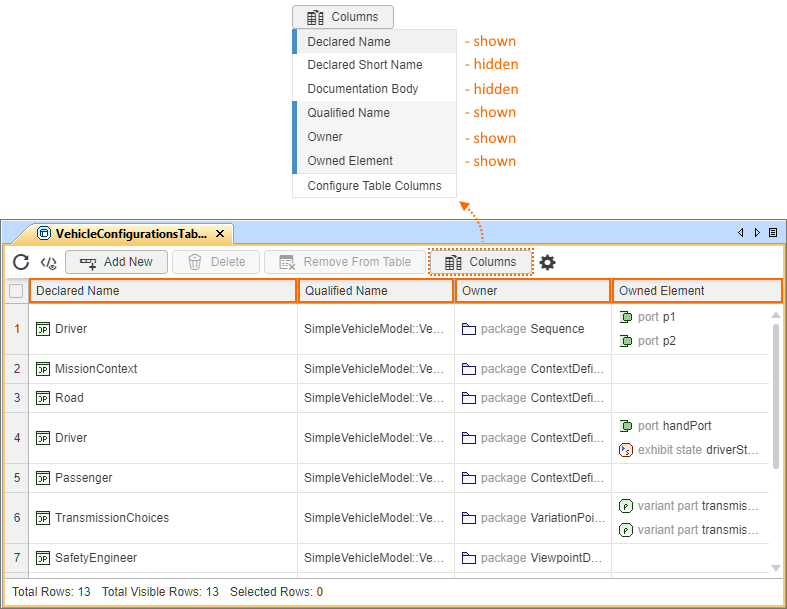
Columns displayed in the table are highlighted in the Columns dropdown menu, while those that are hidden are not.
- The Columns dropdown menu also contains a command for opening the Configure Table Columns dialog, which allows you to:
- Delete existing columns or create columns from the suggested columns list, which includes meta-features. Learn more >>
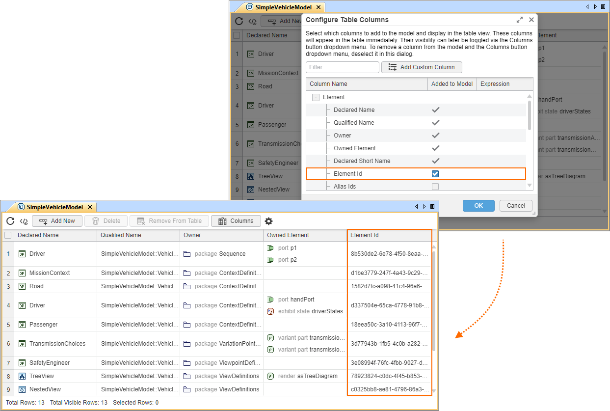
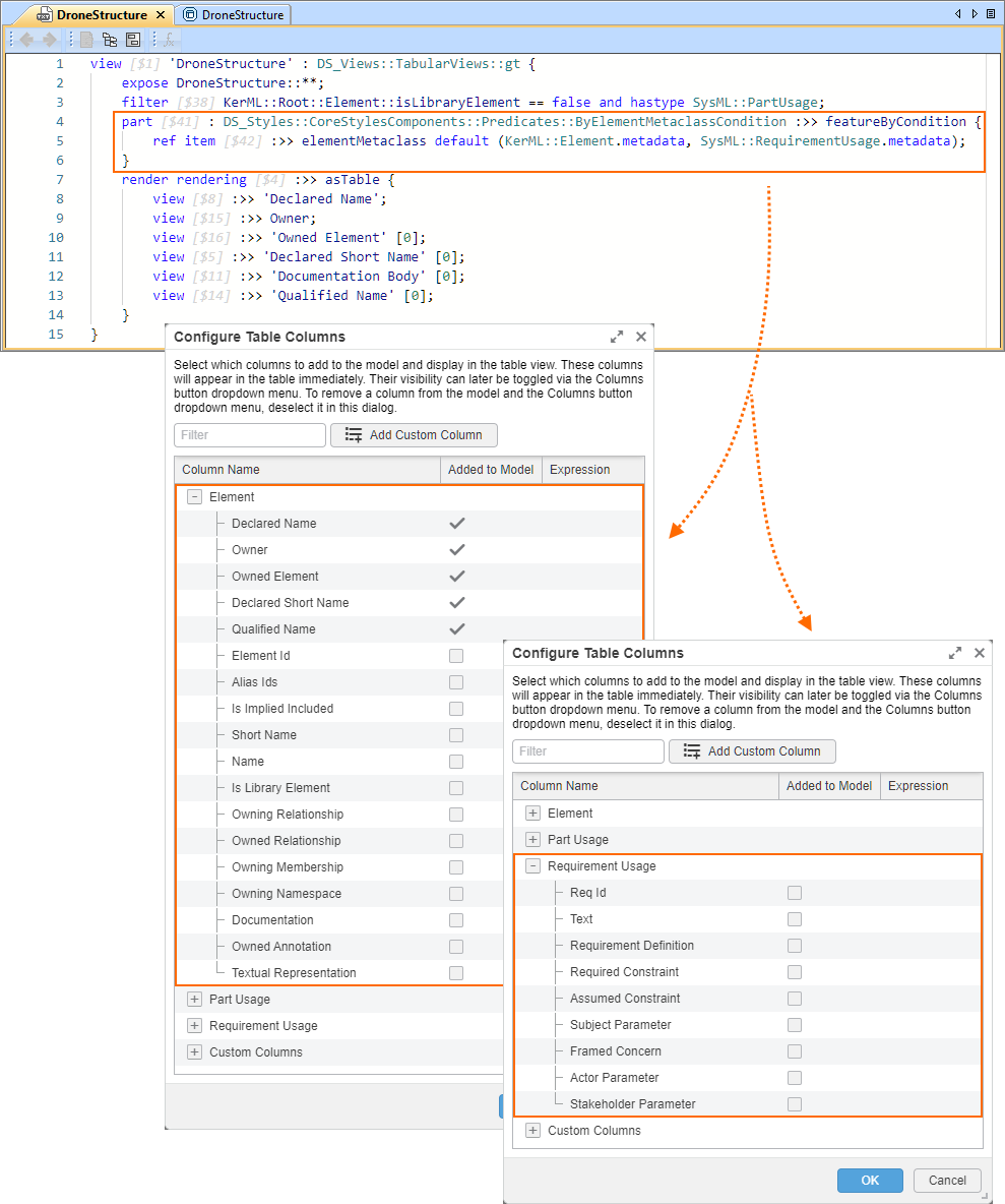
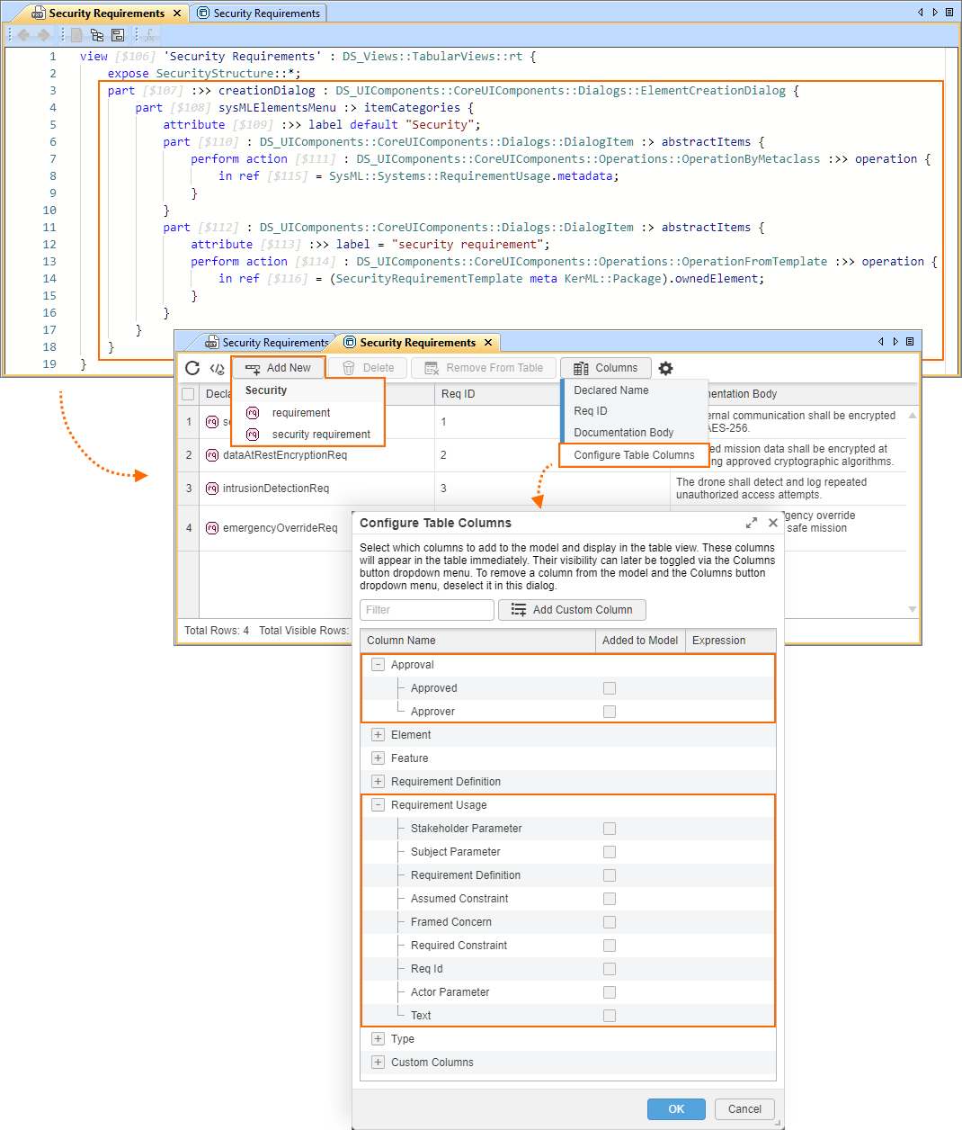
You can customize the suggested column list in the Configure Table Columns dialog for a specific table (tabular view usage or definition). Indicate a specific metaclass or metadata to make it available in the suggested column list, including its meta-features. The meta-features are grouped under the metaclass/metadata and are available for selection. Learn more >>
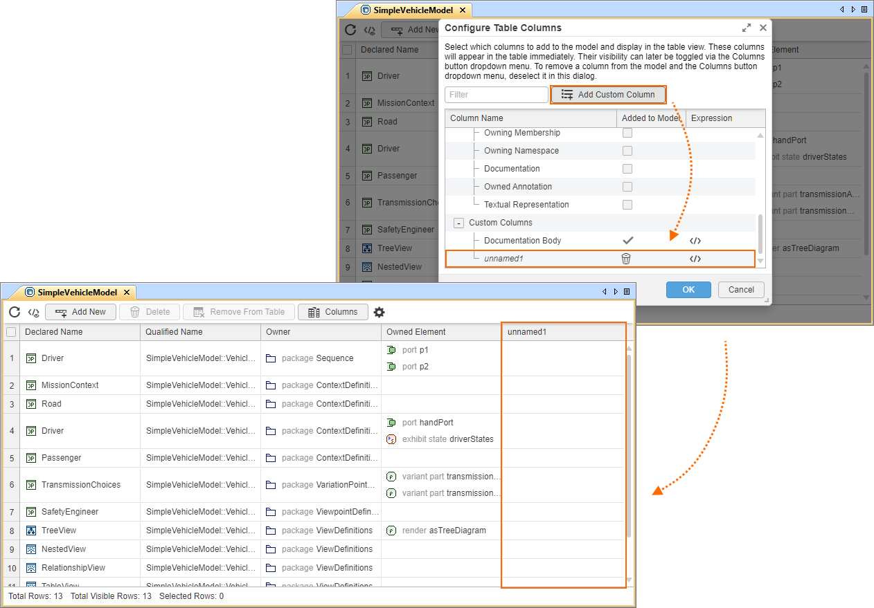
- Create custom columns using the Add Custom Column button. Learn more >>
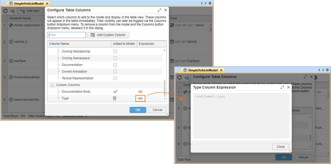
- Preview custom column expressions. Learn more >>
Enhanced ColumnByFeatureView Columns
ColumnByFeatureView columns now support user-defined features. Columns based on user-defined features are editable when their values are of primitive types (String, Integer, Real, or Boolean). This provides greater flexibility when creating tables and enables more efficient editing of column cell values directly within the view. Learn more >>
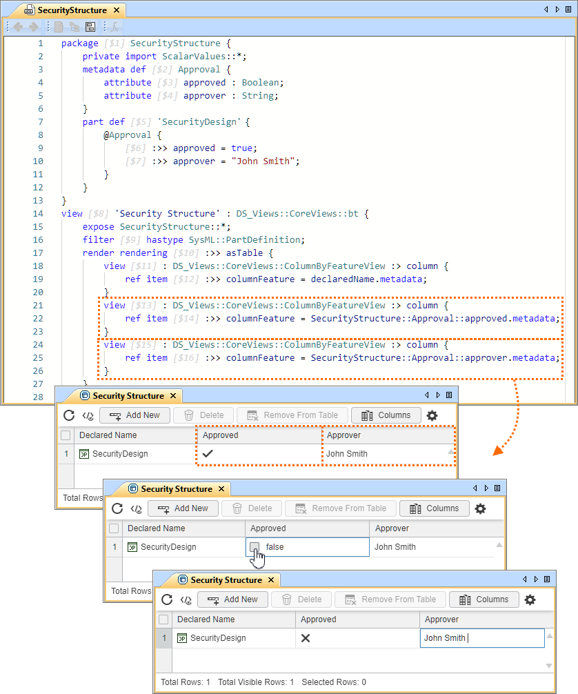
Table Row Management
The tabular view toolbar has been supplemented with new buttons, providing convenient table element management:
- The Add New button displays a dropdown menu for selecting an element to be created in the model and displayed in the table. The tool automatically adjusts the element selection to match the table’s filters. Learn more >>
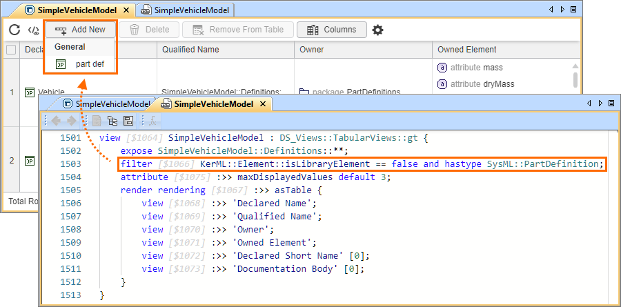
- Although the project’s active Element Creation dialog is used to suggest elements in the Add New element selection dropdown menu, you can customize it by specifying a custom Element Creation dialog for a specific table. The elements you specify for the dropdown menu are also made available as the suggested columns in the Configure Table Columns dialog, including the meta-features of the specified metaclass/metadata. Learn more >>
- The Delete button deletes the selected row elements from the table and the model. The command is also available via the table cell shortcut menu. Learn more >>
- The Remove From Table button hides the selected row elements from the table. This is achieved by filtering out the selected element from the table. The command is also available via the table cell shortcut menu. Learn more >>
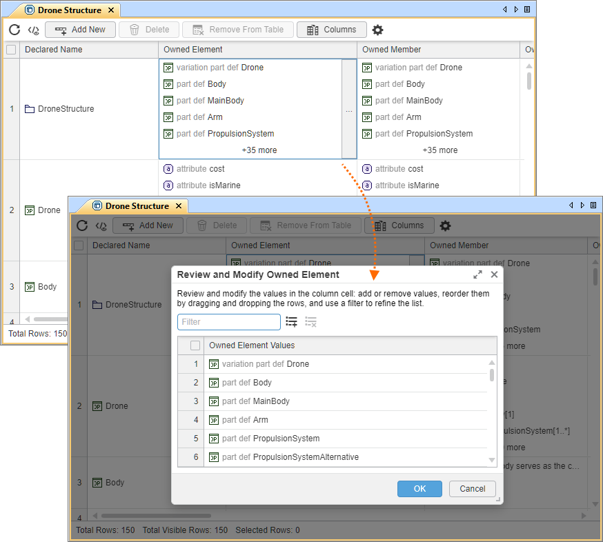
Table Cell Value Management
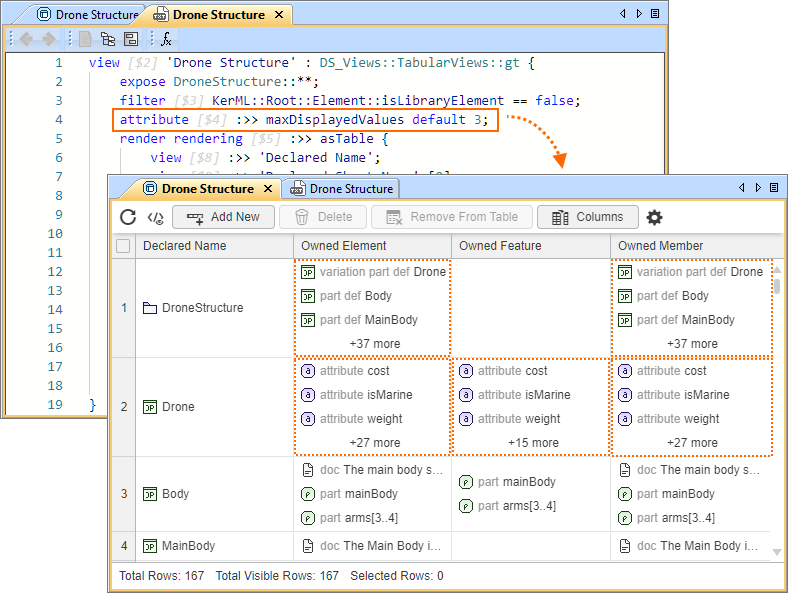
From now on, you can easily manage table cell values. Invoke the Review and Modify dialog from the table cell to review, rename, create, delete, reorder, and filter cell values. Learn more >>
- Although multi-valued cells display up to 10 values by default, you can modify this limit via the maxDisplayedValues attribute. Learn more >>
Other Tabular Views Improvements
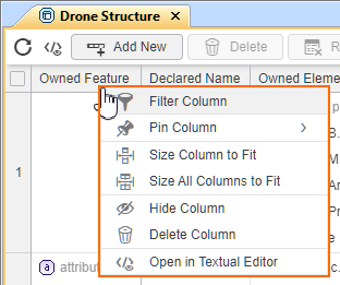
The tabular view's column header shortcut menu has been enhanced with new commands for improved table column management:
- The Pin Column command allows you to pin the column to the left or the right side of the table. Learn more >>
- The Hide Column command hides the selected column from the table's diagrammatic representation without removing it from the model. Learn more >>
- The Delete Column command deletes the selected column from the table and the model. Learn more >>
- The Open in Textual Editor command selects the column in the Containment tree and opens the Textual Editor tab, highlighting the selected column. Learn more >>
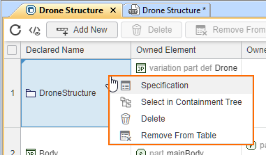
- Additional commands have been added to the table cell shortcut menu for easier table element management:
- The Select in Containment Tree command selects the row element or the cell value in the Containment tree. Learn more >>
- The Specification command opens the Specification panel for the row element or the cell value. Learn more >>
- The Select in Containment Tree command selects the row element or the cell value in the Containment tree. Learn more >>
- You can now add elements to tables by dragging and dropping elements from the Containment tree or element symbols from views onto the diagrammatic representation of a tabular view. Learn more >>
- Tabular views are now limited to displaying up to 50,000 rows. If building a table exceeds this limit, the tool displays a notification suggesting that you narrow the table scope or adjust the display mode settings and try again. Learn more >>
Symbolic Views Improvements
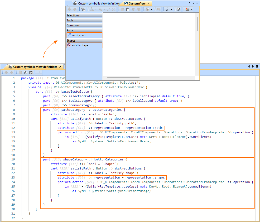
Representation Control for Templated Buttons in Custom Symbolic View Palette
When creating custom symbolic views with custom view palettes, you can now define the representation of elements created via custom templated buttons. The new representation attribute allows you to specify how elements are displayed in the view (for example, as a shape, path, n-ary path, or shape on border). This enables a more precise view customization to match specific modeling needs. Learn more >>
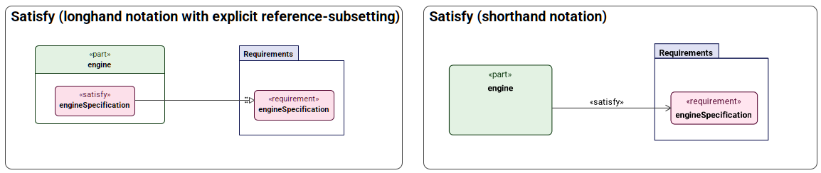
Reference As Path
In SysML v1, traceability relationships such as satisfy, verify, allocate (behavioral), and others were modeled as specialized dependencies between model elements. In SysML v2, these traceability aspects are expressed differently - using a dedicated usage element (e.g., satisfy requirement or perform action) combined with a reference-subsetting relationship to the target element (such as a requirement or action). For example, 'satisfy' is represented by a satisfy requirement usage, where the satisfying element is implied by its owner or subject value, and the satisfied requirement is linked via reference-subsetting. This release adds support for rendering these SysML v2 traceability patterns as paths for event, perform, include, exhibit, satisfy, verify, assume, require, assert, frame, and render. You can now create these elements as paths via the view palette and display them using the dedicated Display References command.
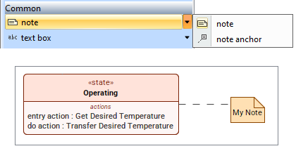
Notes in Views
Notes are now fully supported in SysML v2 views. They can be created directly from the view palette's Common section and displayed in a view. Notes can also be attached to symbols, preserving contextual annotations in the model.
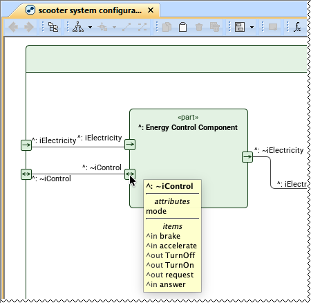
Show Parameter/Port Features in Tooltips
Parameters/Ports on the shape border are rendered as compact symbols, which leaves too little space to show their details directly in the view. This release brings SysML v1-style usability to SysML v2 parameters/ports by displaying nested elements on demand. Hovering over a parameter/port symbol displays a tooltip showing both owned and inherited features, including attributes and items, so you can quickly understand the port’s interface without cluttering the view.
Style Sheets Improvements
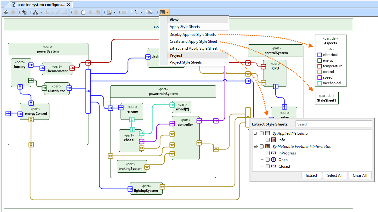
Style Sheet Management in Symbolic Views
You can now create, apply, extract, and display style sheets directly in symbolic views. The Style Sheets command menu in the view toolbar now allows you to:
- Display the style sheets applied to a symbolic view, making it clear which styling rules drive the visualization. Learn more >>
- Create and apply a new style sheet directly from the view, enabling a simplified and efficient workflow. Learn more >>
- Automatically extract style sheets based on the content currently displayed in the view, including applied metadata, metadata feature values, specialized library elements, and library element feature values. This helps capture consistent styling rules with minimal manual effort. Learn more >>
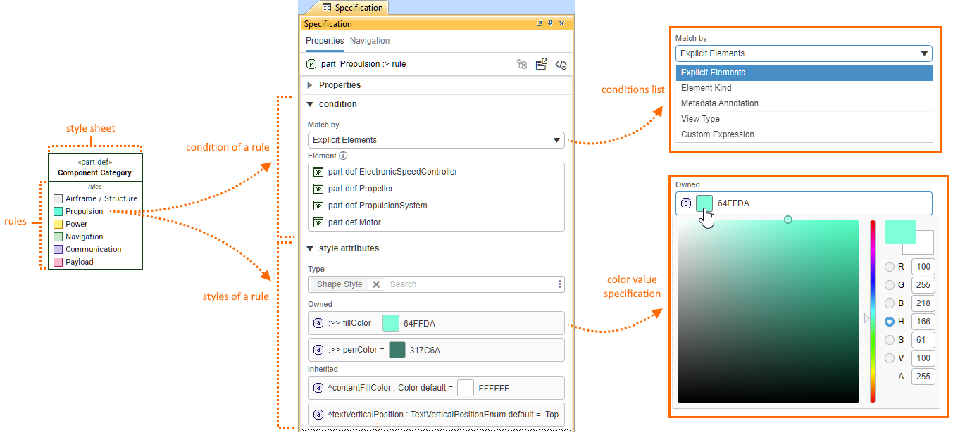
Style Sheet Rule Specification Through the Specification Panel
The Specification panel now makes it easier to review and work with style sheet rules. You can now specify the condition and style attributes of a style sheet rule directly in the Specification panel.
- Easily specify the rule condition as an explicit element, element kind, metadata annotation, view type, or custom expression. Learn more >>
- Customize styles in the Style Attributes section by specifying the required style definitions and modifying owned or inherited style attributes. You can redefine them and assign values using the same workflow as for any inherited SysML v2 attribute. For color properties, a built-in color picker is available for quickly selecting and applying the desired color value. Learn more >>
Creation Dialogs Customization
Model-Based Relationship Creation Dialog
You can now model a custom, model-based Relationship Creation dialog that lists only the relationship creation commands of your choice.
There are two options for customizing the Relationship Creation dialog:
Customize the predefined SysMLRelationshipCreationDialog configuration in the SysML Customization model library. This allows you to inherit its configuration and tailor the Relationship Creation dialog as needed. Learn more >>
Create a Relationship Creation dialog from scratch via the conceptual RelationshipCreationDialog definition. This gives you full control of designing the dialog entirely according to your own needs, without relying on predefined settings. Learn more >>
With either approach, you can define a model-based Relationship Creation dialog that includes only the commands you need, as well as specifying how they are structured into custom command categories. This enables full customization of the dialog to match the needs of your specific project.
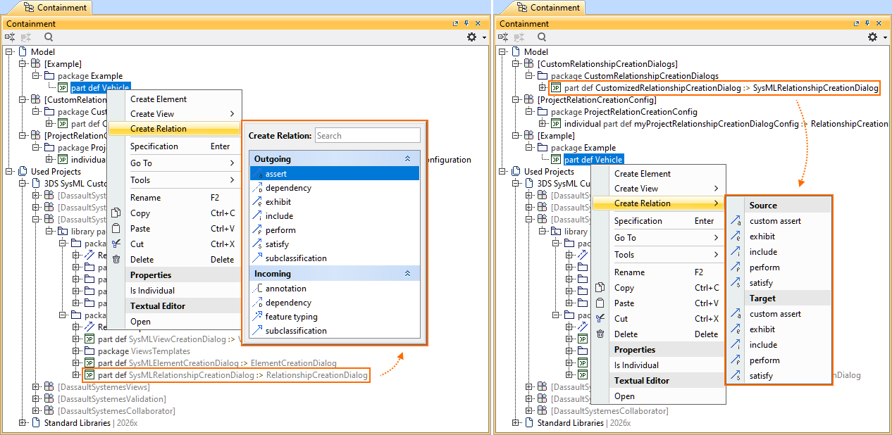
The image on the left shows the Relationship Creation dialog according to the predefined SysMLRelationshipCreationDialog configuration. The image on the right shows the customized Relationship Creation submenu.
Relationship Creation Dialog Management
Additionally, you can activate different Relationship Creation dialog configurations for your project via the Active Create Relationship Dialog. Use the Manage Create Relationship Dialog command from the configuration element shortcut menu or the Active Relationship Creation Dialog project option. While the predefined SysMLRelationshipCreationDialog configuration is enabled by default for all SysML v2 projects, you can easily activate another configuration. Learn more >>
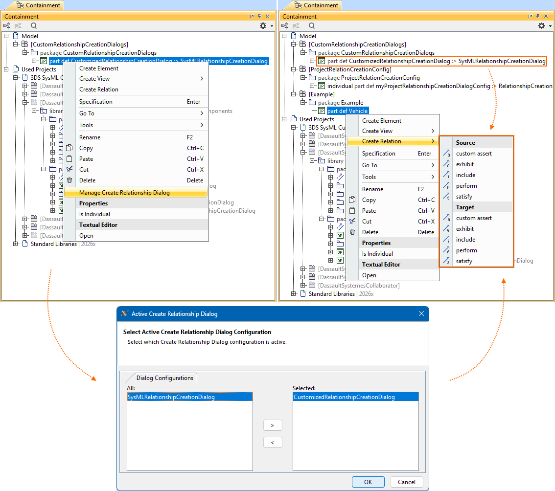
The Manage Create Relationship Dialog command invokes the Active Create Relationship Dialog, where the custom Relationship Creation dialog's CustomizedRelationshipCreationDialog configuration is activated for the project.
Model-Based Element Creation Dialog
You can now model a custom, model-based Element Creation dialog that lists only the element creation commands of your choice.
There are two options for customizing the Element Creation dialog:
Customize the predefined SysMLElementCreationDialog configuration in the SysML Customization model library. This allows you to inherit its configuration and tailor the Element Creation dialog as needed. Learn more >>
Create an Element Creation dialog from scratch via the conceptual ElementCreationDialog definition. This gives you full control of designing the dialog entirely according to your own needs, without relying on predefined settings. Learn more >>
With either approach, you can define a model-based Element Creation dialog that includes only the commands you need, as well as specifying how they are structured into custom command categories. This enables full customization of the dialog to match the needs of your specific project.
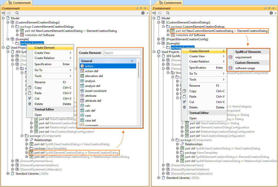
The image on the left shows the Element Creation submenu according to the predefined SysMLElementCreationDialog configuration. The image on the right shows the custom Element Creation submenu.
Element Creation Dialog Management
Additionally, you can activate different Element Creation dialog configurations for your project via the Active Create Element Dialog. Use the Manage Create Element Dialog command from the configuration element shortcut menu or the Active Element Creation Dialog project option. While the predefined SysMLElementCreationDialog configuration is enabled by default for all SysML v2 projects, you can easily activate another configuration. Learn more >>
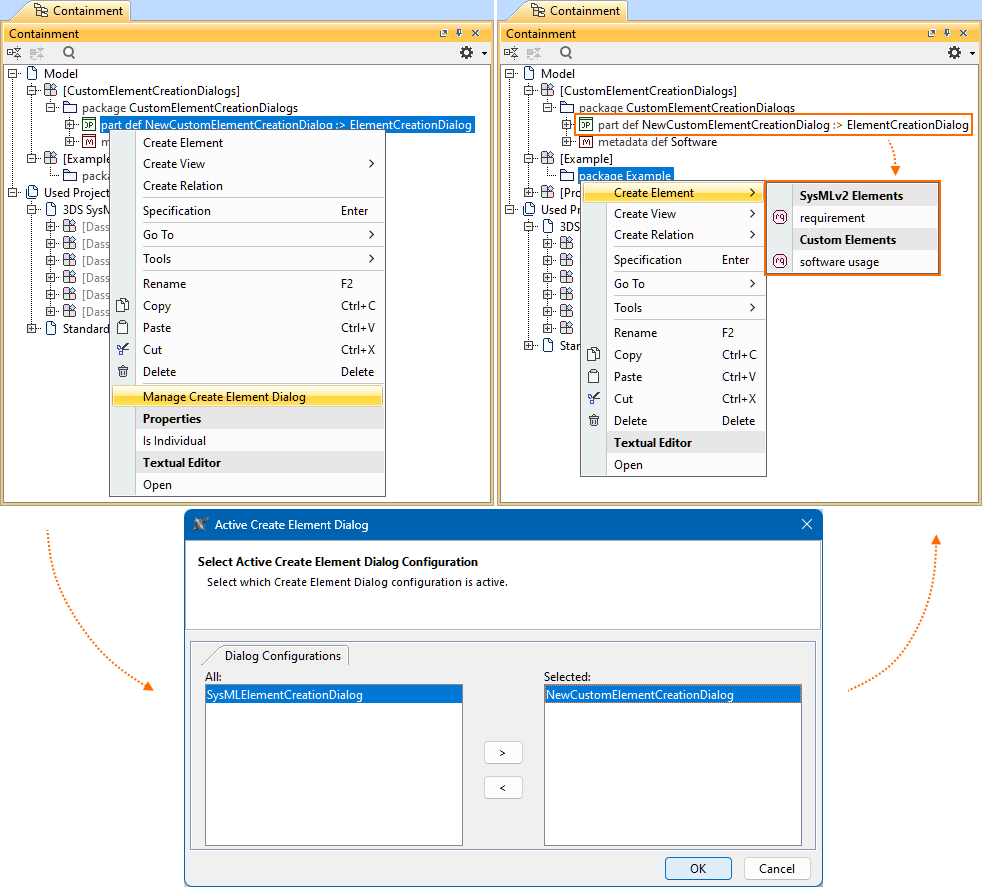
The Manage Create Element Dialog command invokes the Active Create Element Dialog, where the custom Element Creation dialog's NewCustomElementCreationDialog configuration is activated for the project.
Textual Editor Improvements
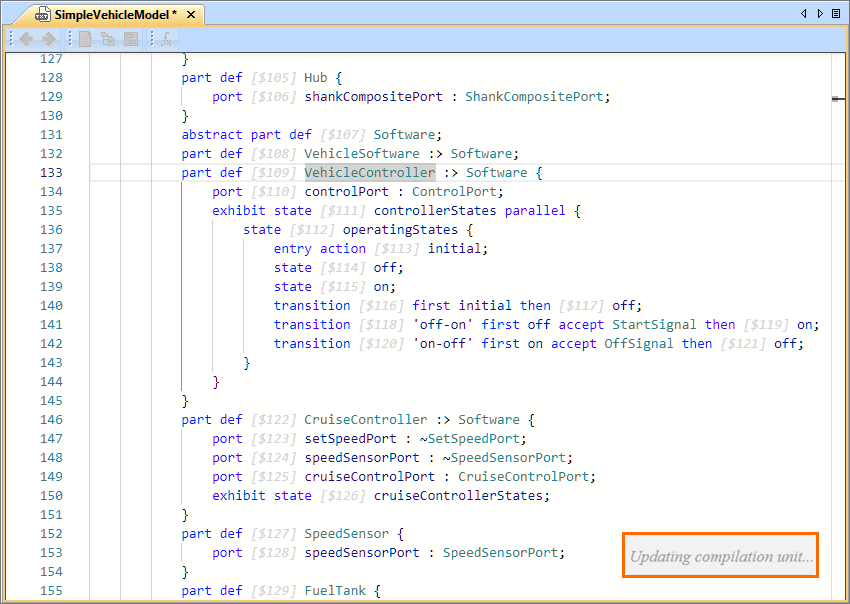
In-Editor Notifications for Background Tasks
When a longer-running background task is in progress, a notification is displayed directly in the Textual Editor. While the notification is active, synchronization and context switching between the Textual Editor and other views are temporarily disabled to prevent conflicting actions. This helps maintain model consistency and prevents unintended user interactions during background processing.
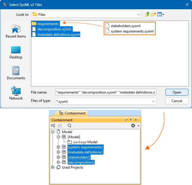
Multiple File Import
The SysML v2 textual notation import now supports importing multiple .sysml files at once, as well as entire directories. This streamlines bulk model import and simplifies working with modularized textual models. Learn more >>
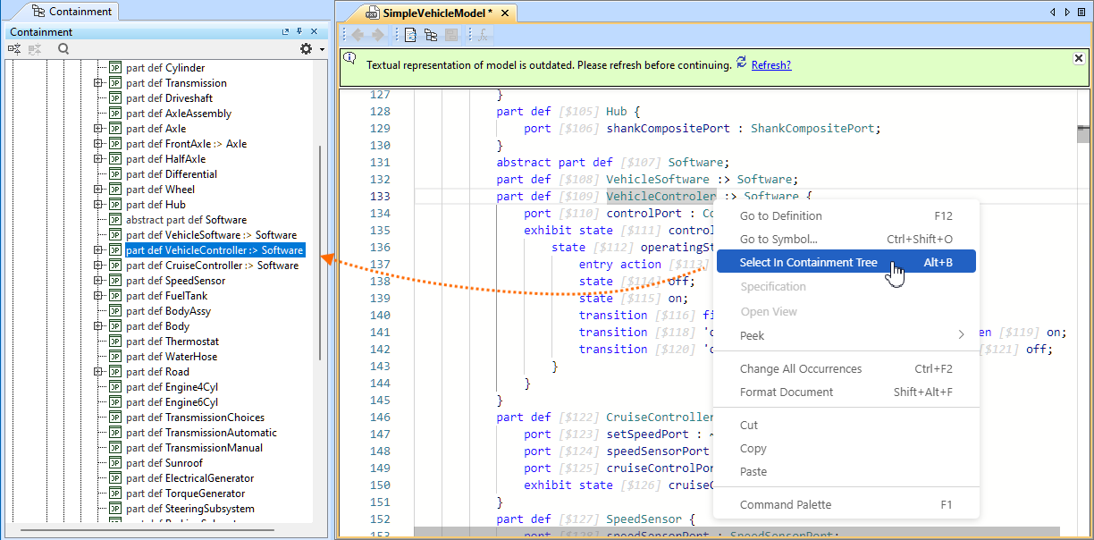
Select in Containment Tree and Cross-Highlighting When the Editor is Not Synchronized
The Select in Containment Tree command now works even when the Textual Editor is not synchronized with the model. If an element is modified outside the Textual Editor (for example, renamed in the Containment tree), you can still target and select the correct element using the command. Similarly, selecting an element in the Containment tree highlights the corresponding range in the Textual Editor, provided the element exists in both. This ensures reliable navigation and element targeting across views, even if the Textual Editor is not synchronized. Learn more >>
Textual Editor Performance Improvements
2026x Refresh1 delivers significant performance improvements in the Textual Editor:
- Synchronization, i.e., the creation or update of the persistent model from the Textual Editor.
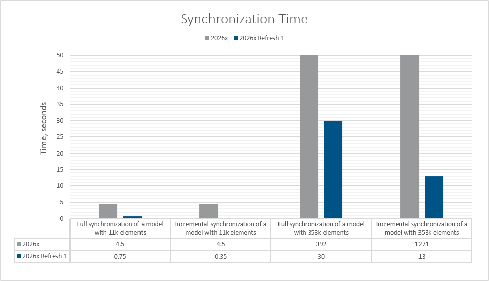 Full synchronization is done when a full model is added to an empty Textual Editor and saved.
Incremental synchronization is done when the existing model is edited and saved in the Textual Editor.
- Textual Editor opening time.
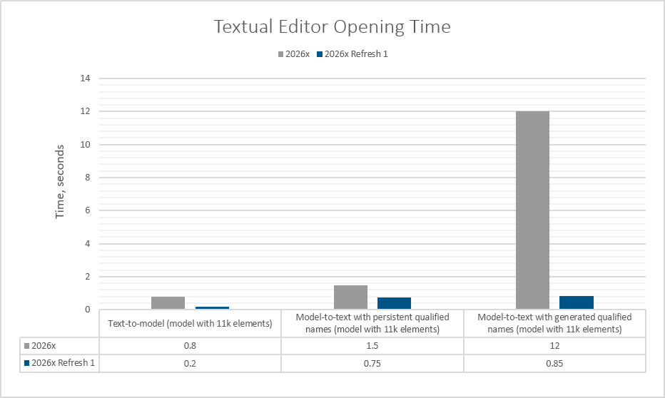
The Textual Editor opening time comprises model-to-text and text-to-model time. Model-to-text covers the transformation from the SysML v2 model to textual notation.
Text-to-model covers the creation of an in-memory transient model from textual notation.
Model-to-text with persistent qualified names means the qualified names are available and can be used during the generation.
Model-to-text with generated qualified names means persistent qualified names are not available and must be generated.
Other Textual Editor Improvements
- A new environment option, Enable Minimap, has been introduced, allowing you to choose whether the minimap should be shown in the Textual Editor. Learn more >>
- Name resolution performance. A new environment option, Name Resolution Mode, allows you to select the desired resolution mode:
- 'Fast' for maximum speed with rare corner-case inaccuracies.
- 'Balanced' for a reliable compromise between performance and accuracy.
- 'Full Precision' for guaranteed accuracy with slower execution.
Learn more >>
Specification Panel Improvements
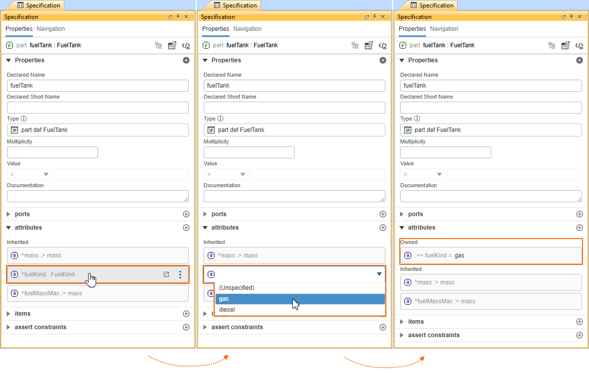
In-Line Value Editor for Compartment Elements
Attributes and ref elements displayed in compartments now support in-line value display and editing in addition to showing their declared names. You can modify values directly within the compartment without navigating to the element itself. Inherited elements are automatically redefined when edited. This simplifies value management and speeds up editing of owned and inherited elements. Learn more >>
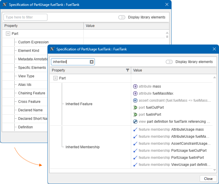
Search Functionality in the Specification Window
The Specification window now includes a search bar, enabling quick and easy search for element properties. Learn more >>
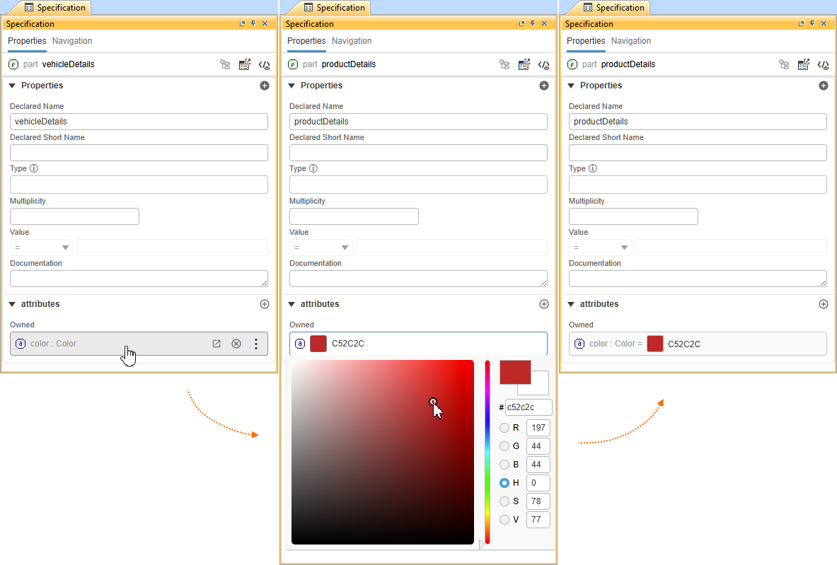
Color Picker Component
Color-typed element values can now be specified directly in the Specification panel using a dedicated color picker in the value editor field. This provides a more intuitive and precise way to define color values. Learn more >>
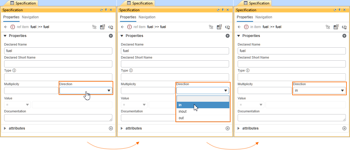
Element Direction Management
The Direction property for item, attribute, and ref elements can now be specified directly in the Specification panel. This streamlines property management and reduces the need for additional navigation. Learn more >>
Other Specification Panel Improvements
- Open elements and expressions in the Textual Editor. You can now open the Textual Editor directly from the Specification panel's Navigation bar. You can also open it for compartment elements, elements specified in the Type field, and Result Expressions. Learn more >>
- Single-type unspecification. When multiple types are set for an element, you can now unspecify a single type without affecting the others. Learn more >>
- Value editor improvements. The Value field now uses an editor appropriate to the specified attribute definition's type. Learn more >>
- Responsive Documentation and Expression fields. The Documentation and Result Expression fields automatically adjust to their content (up to five lines) for improved readability.
- Metadata compartment visibility. The Metadata compartment is now always displayed when at least one metadata definition is applied to an element.
- Compact hints. Hints are now more compact and no longer occupy unnecessary space in the Specification panel.
SysML v1 to SysML v2 Migration Improvements
The SysML v1 to SysML v2 Migration Plugin has been enhanced to migrate symbolic diagrams into corresponding SysML v2 views. Diagrams for Requirements, Use Cases, States, and other symbolic diagram types are now automatically transformed into their SysML v2 view equivalents. All symbolic view types and symbols currently supported by the CAMEO SysML v2 solution are included, ensuring improved visual and structural continuity between SysML v1 and SysML v2 models.
Element order is now preserved during migration. This maintains the original model structure, improves traceability, and significantly reduces the need for manual reordering after migration.
Additionally, the migration plugin now supports:
States migration – State elements and related structures are migrated to SysML v2, improving support for state-based behavioral models.
Parametric models migration – Migration now supports parametric elements, including constraint blocks, parameters, properties, and constraints.
Trace relationships migration – Migrated as SysML v2 dependencies.
Stereotypes and primitive tagged values migration.
Variables migration.
TimeExpression, TimeEvent, and ChangeEvent migration.
Allocation relationships migration – Logical, functional, and physical mappings are retained.
Behavioral elements migration – Opaque behaviors and opaque actions are supported.
Object flows migration – Object flows from Activity parameter nodes are supported.
Units migration (core support) – Commonly used units, including core SI units, are mapped.
Learn more >>
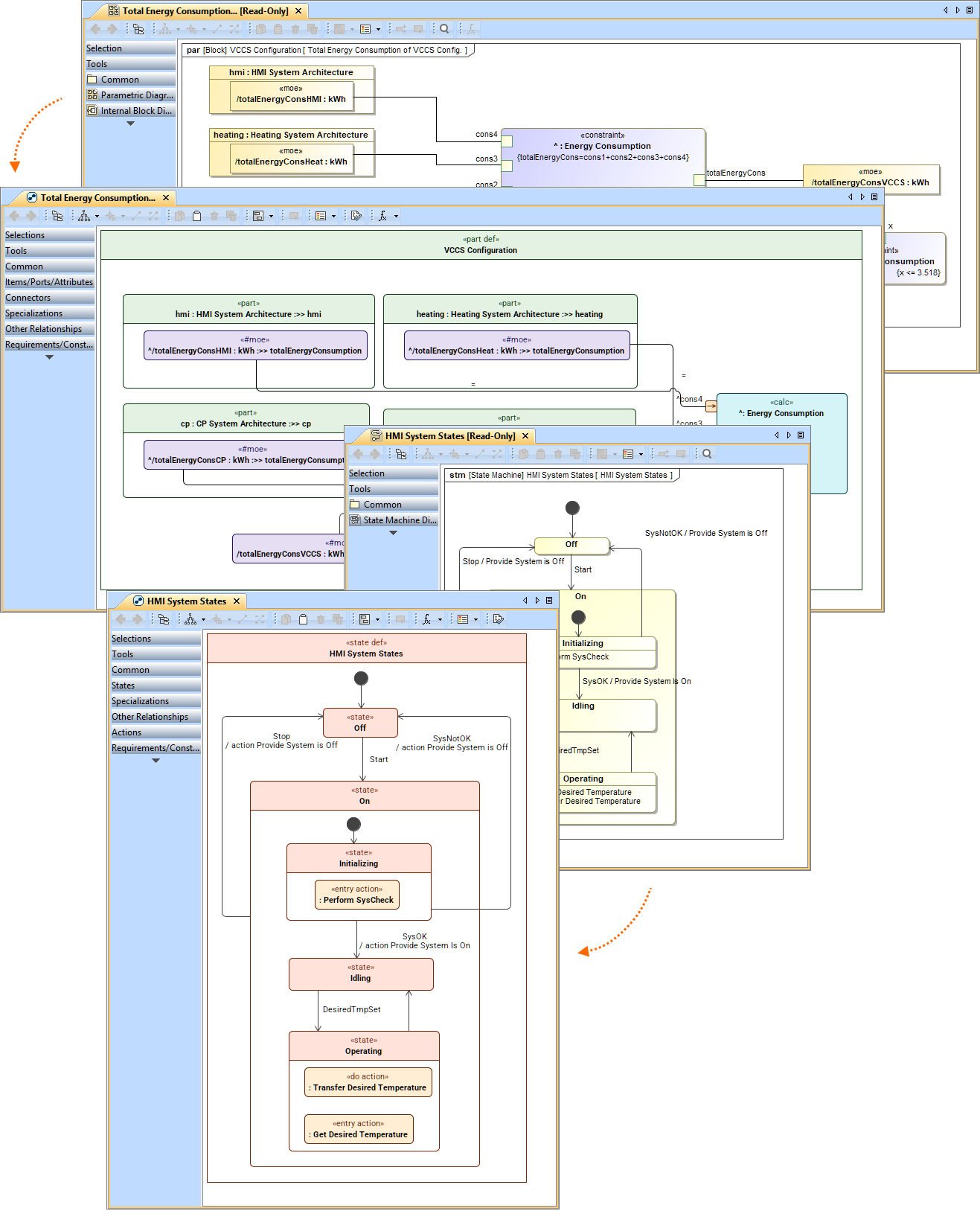
The image displays symbolic diagram migration for SysML Parametric and State Machine diagrams.
SysML v2 Open API
The SysML v2 Open API is now available as a technology preview, providing programmatic access to key SysML v2 modeling capabilities. As SysML v2 support continues to evolve, the Open API should be considered preview functionality and may be refined or changed in future releases. We encourage you to explore the API and share your feedback as this capability continues to mature.
Other SysML v2 Plugin Improvements
- Dynamic baseType evaluation for semantic metadata. The baseType of semantic metadata can now be specified using complex expressions. The expression is evaluated after the metadata is applied, and the returned type is then used as the base type. This is important for advanced metadata library development and usage, such as the next-generation UAF.