Overview
A Component diagram falls under the structural diagramming family. A Component diagram represents pieces of software in the implementation environment in terms of code components.
A Component contains information about the logical Class or Classes that it implements, thus creating a mapping from a logical view to a component view. Dependencies between the Components make it easy to analyze how a change in one component affects the others. The Components may also be shown with any of the Interfaces that they expose. They, as with almost any other model elements, can be grouped into Packages, much like Classes or Use Cases.
Purpose
A Component diagram models the implementation view. It is used in the later phases of the software development when there is a need to divide up Classes among different Components. When working with the CASE facilities, the Components are used for file-class mapping during code generation, reverse engineering, and round-trip engineering operations.
Usage
A Component diagram can be used to:
- analyze system components and how they relate
- analyze system's physical structure
- understand the exact service behavior provided by software.
Summary
Component diagrams are valuable because they:
- reveal possible software configuration issues
- provide an accurate picture of existing systems prior to making changes/enhancements
- model the real software in the implementation environment
- help to reveal bottlenecks in an implementation.
As of MagicDraw 17.0.1, the Component diagram (or the Deployment diagram) replaces the Implementation diagram, which is no longer supported in UML standard. An Implementation diagram created with earlier versions of MagicDraw, now opens as
- Deployment diagram, if Nodes were used in the Implementation diagram
- Component diagram, if Nodes were not used in the Implementation diagram
Customized diagrams that were based on the Implementation diagram are now based on the Component diagram.
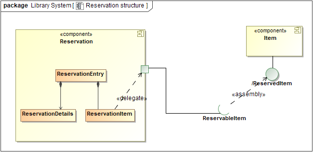
Example of a Component diagram
Related pages