On this page
Introduction
SysML Parametric Diagrams provide a way to integrate engineering analysis models described in mathematical equations and constraints, with design models describing the structural and behavioral aspects of systems. Parametric diagrams include usages of constraint blocks to constrain the properties of another block. A constraint property is a property of any block that is typed by a constraint block. To empower the constraint expression to perform calculations, you have to specify what system parameters should be consumed as variables of that constraint.
See the figure below, as example of SysML Parametric Diagram wherein all elements are highlighted: Value Properties, Constraint Block, Constraint Property, Constraint expression, Constraint Parameter, Binding Connector.
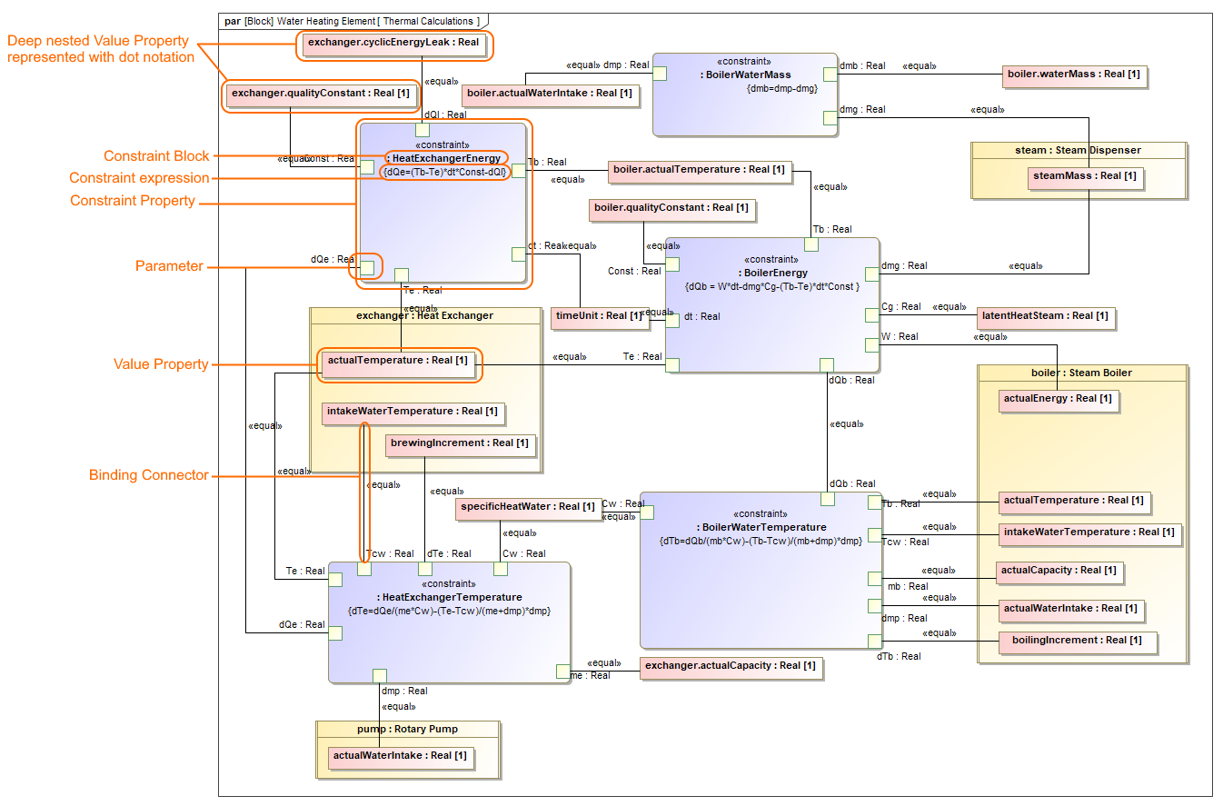
The main elements used in the SysML Parametric Diagram.
Creating parametric constraints
This section explains how to model system constraints in the SysML Parametric Diagram. Parametric constraints are formulas, and parameters are variables that can be bound to value properties later. Variables can be inputs and outputs of the formula. In general, you must perform the following steps to model your system constraints. However, some actions may already be done in the model creation process, so you may skip these steps and use existing model data. The following procedure provides the main workflow of modeling parametric constraints manually and automatically.
There are two ways to model parametric constraints:
- Manually by creating elements and binding them.
- Automatically by using the Parametric Equation Wizard.
Creating parametric constraints manually
To create parametric constraints manually
- Open existing project or create new.
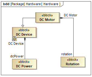
- Create a Block or it's structure in Block Definition Diagram. As shown in the figure, The DC Motor Block is decomposed into Rotation part and inherited DC Power part from DC Device Block. Learn more how to decompose Blocks >
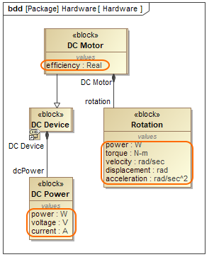
- Create Value Properties for those Blocks. As shown in the figure below, the highlighted Value Properties created for the DC Motor, Rotation and DC Power Blocks. Specify their types.
- Right-click the Block and select Create Diagram > SysML Parametric Diagram. In the opened Display Parameters/Properties dialog, select either:
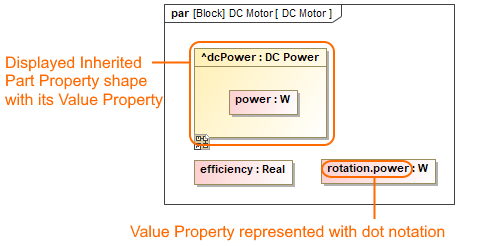
- Part Properties with its Value Properties, if you have enough space on the diagram pane to display part shapes. As example, see the following figure where power Value Property is displayed inside inherited dcPower Part Property shape.
- Only Value Properties, if you need to save a space on the diagram pane. The dot notation is used in Value Property name instead of part shape. As example, see the following figure where dot notation (rotation.power) is used to express the path of power Value Property.
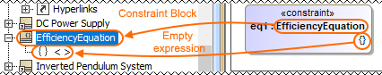
- Click the Constraint Property button on the diagram palette and then click the empty place of that diagram pane. An unnamed Constraint Property is created. Type its name.
- Specify Constraint property type by selecting the Constraint Property shape, from the smart manipulator toolbar, click
 and do either:
- Type a name of a Constraint Block and press Enter. The new Constraint Block is created automatically in the model with an empty Constraint expression.
Double-click {} and type an expression. To make a reusable Constraint Block, we highly recommend to use different value names than exist in particular model. E.g. efficiency=powerOutput/suppliedPower. Create parameters automatically from equation by clicking from Constraint Property smart manipulator toolbar. As shown in the figure below, three Constraint parameters are created: efficiency, suppliedPower, powerOutput.
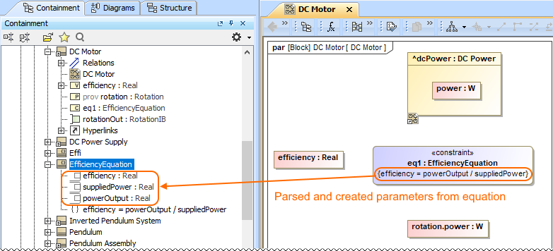
- Select reusable Constraint Block from the library. The Constraint expression appears automatically.
- Type a name of a Constraint Block and press Enter. The new Constraint Block is created automatically in the model with an empty Constraint expression.
Connect Value Properties with Constraint Parameters in one of the following way:
- Select the Value Property shape, from smart manipulator toolbar click and connect it to a Constraint Property shape. From the Select Parameter menu list, select an appropriate parameter. As example, see the figure below where power Value Property is binding by selecting a supplierPower parameter from the suggested list.
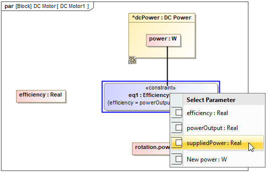
- Display Constraint Parameters on Constraint Property shape by clicking smart manipulator toolbar. Select Value Property/Constraint Parameter shape, click and connect it to Constraint Parameter/Value Property. As shown in the figure elow, the efficiency Value Property is binding with an efficiency parameter.
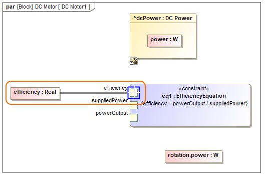
The Constraint Parameter are connected with Value Properties using Binding Connector. Now you can run the simulation of parametric data in one of the following way:
- Right-click the Block that owns the Parametric diagram and select Simulation > Run.
- From the Parametric Diagram toolbar, click .
.
In the Variables tab, type values and click . Learn more about parameters simulation >
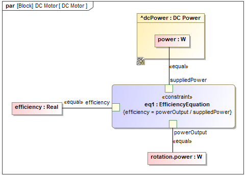
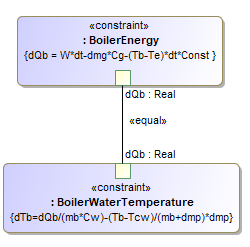
You can create an equation system by creating bindings between parameters between separate Constraint Properties. E.g. The BoilerEnergy and BoilerWaterTemperature Constraint Properties are connected through the dQb parameter because the BoilerEnergy constraint expression provides a value for the BoilerWaterTemperature constraint expression.
Creating parametric constraints automatically
To create parametric constraints automatically
- Open existing project or create new.
- Create a Block or it's structure in Block Definition Diagram. As shown in the figure, The DC Motor Block is decomposed into Rotation part and inherited DC Power part from DC Device Block. Learn more how to decompose Blocks >
- Right-click the Block for which you want to create SysML Parametric Diagram, select Tools > Parametric Equation Wizard. Learn more about Parametric Equation Wizard >
- Type equation and click the Parse and Map button. The Constraint Block with parameters are created automatically. If the names of Constraint Parameter and Value property are the same, they and mapped automatically. You can change bindings by dragging Constraint Parameters in the left tree onto properties in the right tree. Learn more about creating Parametric Diagram from an equation >
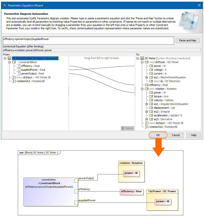
- In the SysML Parametric Diagram toolbar, click
 to remap or include additional Value Properties.
Related pages
- Defining Constraint Blocks
- SysML Parametric Diagram context
- Creating Constraint Parameters automatically
- Extracting Constraint from Requirement
- Parametric Equation Wizard
- Displaying parameters and properties
- Creating Binding Connector
- Creating reusable constraint libraries
- Wrapping MATLAB functions
Sample model
The model used in the figures of this page is the InvertedPendulum sample model that comes with SysML plugin. To open this sample do one of the following:
- Download InvertedPendulum.mdzip.
- Find in modeling tool <modeling tool installation directory>\samples\sysml\Inverted Pendulum\InvertedPendulum.mdzip.