Page History
The recording capability of the Cameo Simulation Toolkit allows you to:
- record created objects as CreateMessages connected between Lifelines that represent the object creator and features of the created object respectively.
- record signals as SendMessages connected between Lifelines that represent signal senders and signal receivers respectively. Connectors will be assigned to the messages if signals are sent via ports or connectors.
- record operation calls as CallMessages connected between Lifelines that represent operation caller callers and operation owners respectively. Connectors will be assigned to messages if operations are called via ports.
- record changes of states and primitive values as StateInvariants on Lifelines that represent features of objects that own the states or the values.
This section demonstrates how to record the signal, state change, operation call, and value change as a sequence diagram during a model simulation. The sample StereoSystemFlashingLight.mdzip, located in the the <md.install.dir>/samples/simulation/ directory, will be used throughout this section.
...
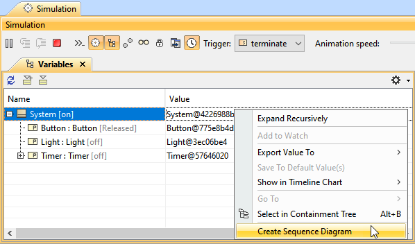
- In the Variables pane, select and right-click a runtime object.
- Click Create Sequence Diagram on on the context menu (see the following figure). An empty sequence diagram will be created.

Shortcut menu that can be accessed from the simulation console.
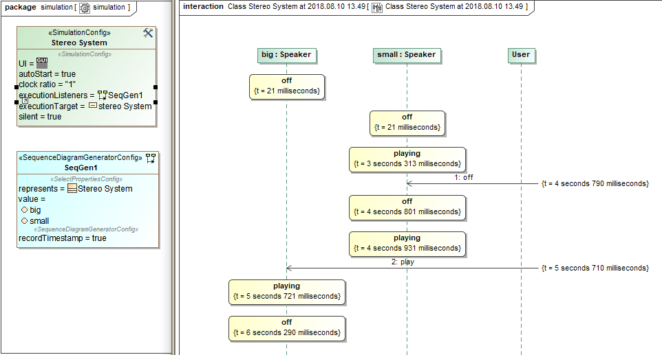
Whenever you simulate a model (for example, Stereo System such as Flashing Light as shown in the figure above), Cameo Simulation Toolkit will:
- create the first Lifeline, which represents the selected runtime object.
- record each signal sent from the selected runtime object as a Message in the sequence diagram.
- record each operation call caused by a call message, a CallOperationAction, or a an ALH.callOperation with argument and return value as messages in the sequence diagram.
- record an object that receives a signal and(/or ) an operation call as a Lifeline, unless . Unless it exists in the diagram, the object will be called a 'lifeline object'.
- record each change in the state of a lifeline object as a StateInvariant on the Lifeline, with the changed state symbol.
- record each change in the feature value of a lifeline object as a StateInvariant on the Lifeline. Changes in value are enclosed in constraint brackets, for examplei.e., {a=10}.
| Note | ||
|---|---|---|
| ||
StateInvariants are designated by yellow rounded rectangle symbolsrectangles. See the following figure for examples. |
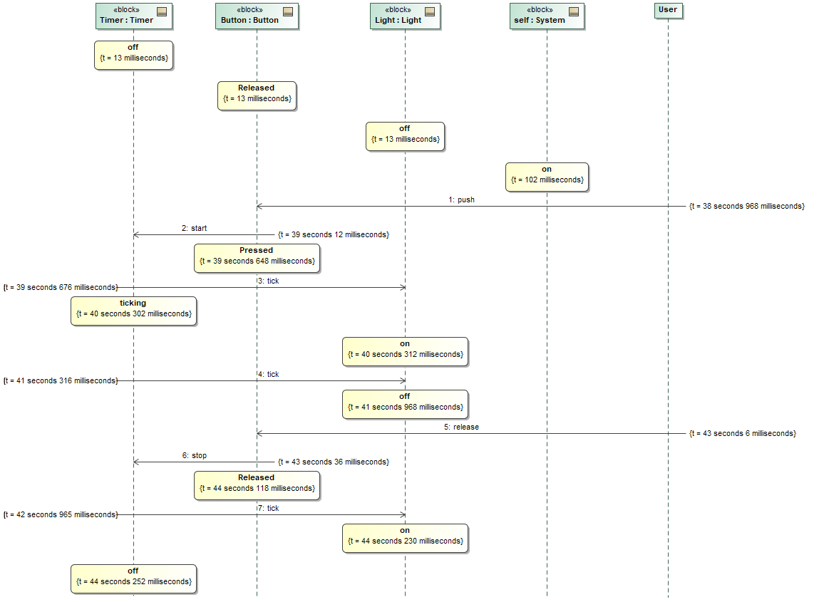

A sequence diagram depicting call messages running between lifelines.
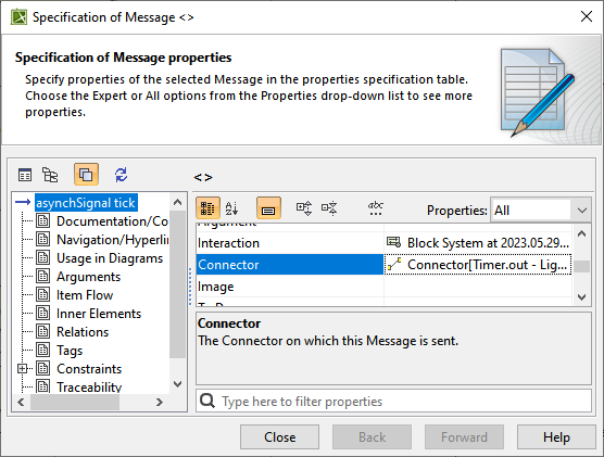
To see what connector a signal or an operation call is sent through through
...
- Double-click the message or right-click it and select Specification to open the specification window.
...
To see the values of arguments sent with a signal or an operation call
...
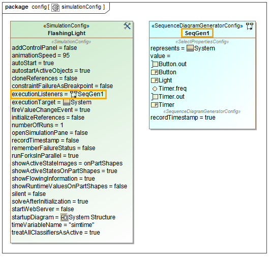
You can customize recorded messages (signals) and lifelines using a SequenceDiagramGeneratorConfig.
 and Lifelines")
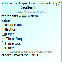
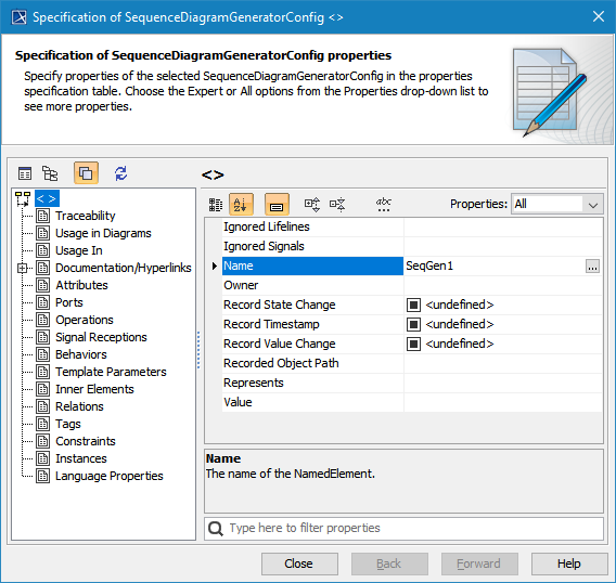
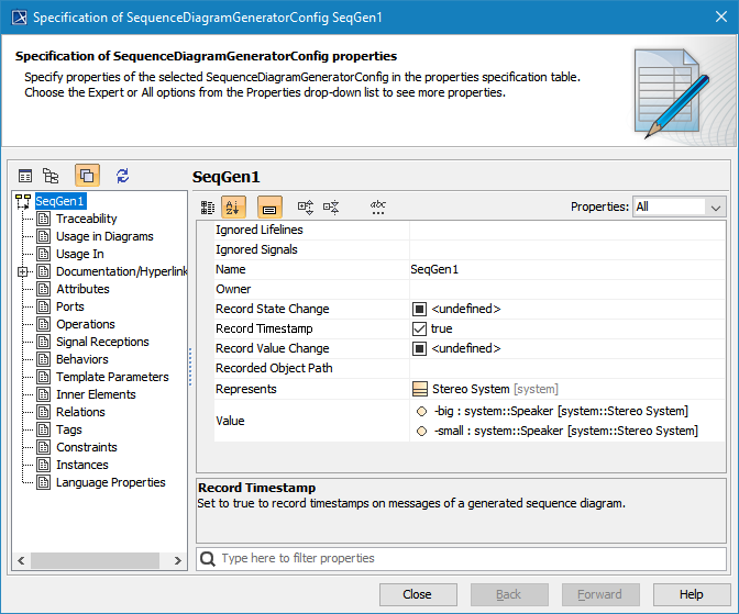
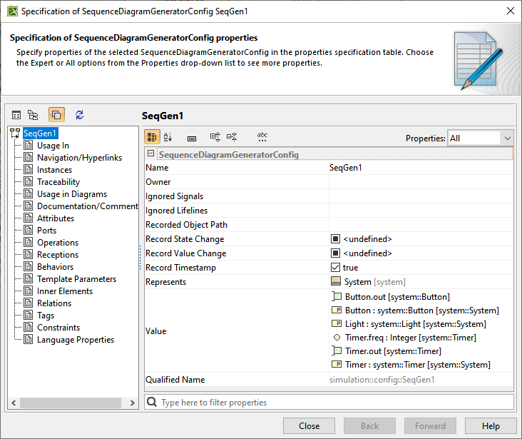
A SequenceDiagramGeneratorConfig element showing its parameters.
A A SequenceDiagramGeneratorConfig is a stereotype that is inherited from an ExecutionListener stereotype. It contains the following six tag definitions:
- ownerOwner
It is an An element that owns a generated Interaction element. A generated Sequence diagram will be created under that particular Interaction element. You need to select only the element that can own an Interaction element; otherwise, otherwise a model inconsistency will occur.
- ignoredSignalsIgnored Signals
They are signals Signals that will be ignored (will not be recorded) during a simulation recording.
- ignoredLifelinesIgnored Lifelines
They are a A list of elements (objects) that will be ignored (will not be recorded as lifelines) during a simulation recording. This list takes priority over the value list. - recordedObjectPathRecorded Object Path
It is used Used to specify a property path to an object that will be recorded by a sequence diagram generator. The path must start from a property owned by either a classifier , which is the target of the simulation configuration, or a classifier of an instance specification , which is the target of target of the simulation configuration. The property at each successive position following the first position must be contained in the classier classifier that types the property at the immediate immediately preceding position. - recordStateChangeRecord State Change
This is a A boolean option. If true, state changes will be recorded. - recordValueChangeRecord Value Change
It is a A boolean option. If true, value changes will be recorded. - recordTimestampRecord Timestamp
It is a A boolean option. If true, timestamps will be recorded on messages. - Valuevalue
Structural A structural feature which whose value is represented for by the configuration.
You can specify the default values of recordStateChange, recordValueChange, and recordTimestamp through the Project Options dialog dialog. The values in the project options will the project options will be used instead if the tagged values of the sequence diagram generator are not specified. The default values of these project options are these project options are true, true, and false (see the following figure). True means all values will be recorded by default.
...
To customize a Sequence diagram recording
...
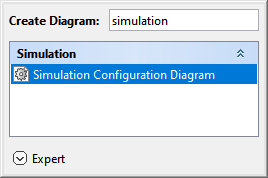
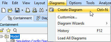
- Create a Simulation Configuration Diagram by doing one of the following:
In the Containment tree, right-click the Model folder (root folder) and select Create Diagram.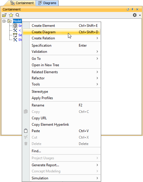
- Do one of the following:
- In the dialog, expand Simulation and selectSimulation Configuration On the main menu, select Diagrams > Create Diagram.
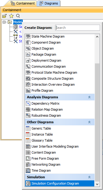
- In the
- search tab, type the keyword simulation and then select Simulation Configuration Diagram.
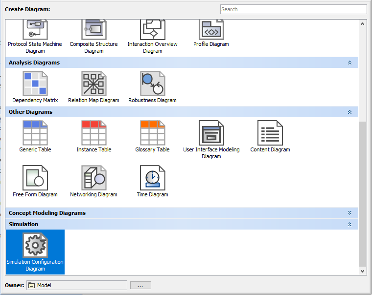
- In the dialog, expand Simulation and selectSimulation Configuration On the main menu, select Diagrams > Create Diagram.
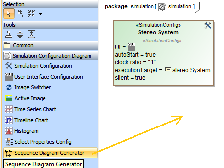
- From the Simulation Configuration Diagram palette, drag the Sequence Diagram Generator to the diagram pane.
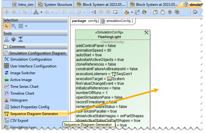
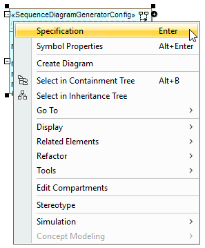
Right-click the newly created SequenceDiagramGeneratorConfig and select Specification to open its Specification dialog.
Specify the value(s) of the tag definition(s) of the config, e.g., Name.
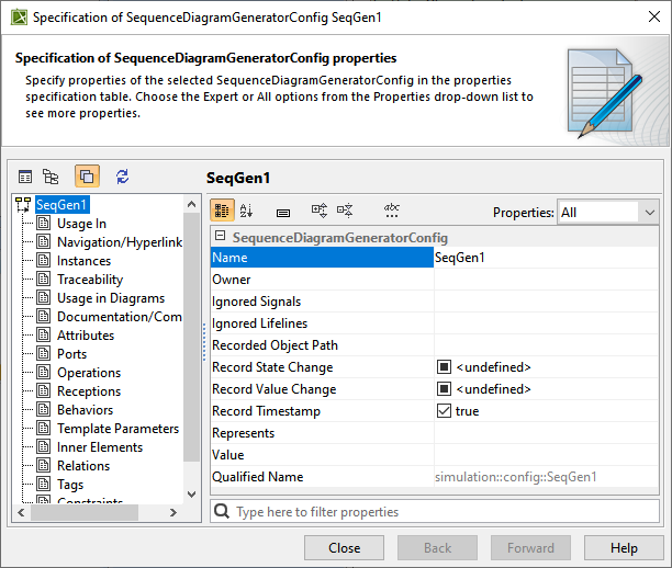
Tip title Tip You can specify Represents and Value to be captured by the SequenceDiagramGeneratorConfig along with other settings, e.g., such as RecordTimestamp.
- Drag the configured SequenceDiagramGeneratorConfig to the SimulationConfig element (see SimulationConfig stereotype). The executionListeners tag of the SimulationConfig will be shown with the specified name of the SequenceDiagramGeneratorConfig, as shown below.