You can represent the same Class with a different appearance according to the context of Class usage in the Composite Structure diagram. To accomplish this, define multiple diagrams for the same Class element with different names, and set them as layout templates. The diagram names identify the differences between layout templates and simplify layout template selection when applying it. The procedures below explain how to create and apply multiple layout templates.
To create multiple layout templates
Create the Class diagram with a name that identifies the layout template name.
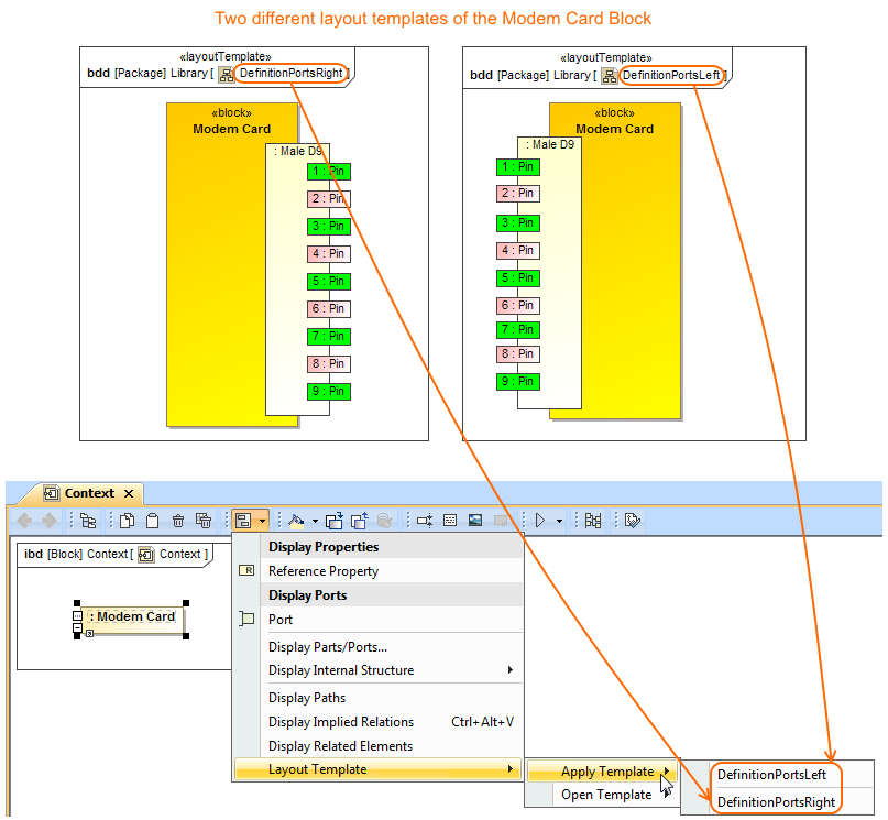
The example below shows how the port's position on the Modem Card Block is represented differently: on the left side and on the right side of the Block shape. According to the illustration, the names of the Block Definition Diagrams are appropriate: DefinitionPortsRight and DefinitionPortsLeft. You can find the same layout templates when trying to apply one of those layout templates for the Part shape in the Internal Block Diagram.
Two different layout templates of the Modem Card Block can be found as selection when applying it in any Internal Block Diagram. The illustration displays concepts from SysML Plugin.
Info
title
Composite Structure Diagram as a layout template
From the version 19.0 SP1, you can define the appearance and layout of a Part Property with its Ports in the Composite Structure Diagram and set this diagram as layout template.
If a Composite Structure Diagram displays several Part Properties, create a layout template directly from a particular Part Property. It's appearance and layout will be copied to the template automatically.
Content block
id
59508978
Sample model
The sample models used in the figure of this page are Modem Cable that comes with SysML Plugin. To open those samples properly you need to install the SysML plugin in the MagicDraw and download Modem Cable Layout Templates.mdzip.