Versions Compared

Key

  • This line was added.
  • This line was removed.
  • Formatting was changed.
Content layer
id372507889
Content column
id372507891
Content block
id372507890
Excerpt

Messages in Communication diagrams can only be depicted on connectors; thus, you should draw a connector before assigning a Message to it.


The following steps show you how to work with messages:

Table of Contents

Assigning a message to a connector

Anchor
assign
assign
To assign a message to a connector


  1. On the diagram palette, click the button corresponding to the desired Message type.
  2.  Click a desired connector on the diagram pane. A Message arrow will be placed on the selected connector.

    Note

    A Message flow has two directions: right and left. Choose one of them by clicking the associated button on the diagram palette.

    Image Modified

Setting/removing the advanced numbering of messages

Anchor
set_remove
set_remove
To set/remove the advanced numbering of messages


  1. From the diagram shortcut menu, select Numbering.
  2. Select to set, or clear to remove the Use Advanced Numbering.

Changing current message numbering

To change current message numbering


  1. From the diagram shortcut menu, select Numbering > Change Numbering.
  2. Increase, decrease, and / or change the level of numbering in the Change Communication Numbering dialog.
    Change Communication Numbering dialogImage Modified


Note

If the Edit button is inactive, remove the automatic advanced numbering of Messages.


Displaying messages

If you want to display messages on connectors in the Communication diagram you must first implement the following conditions (see the figure below):

The Loan Library Item Communication diagram which contains two lifelines and the connector between them.Image Modified


To display messages


  1. Select the connector between lifelines.
  2. Perform one of the following actions:
    • Right-click the connector to open the shortcut menu, and select Display > Display Messages.
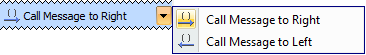
    • On the diagram toolbar, click DisplayImage Modified,and select Display Messages.
    The Display Message command.Image Modified
  3. In the opened Select Messages dialog, select the messages you want to display, and click OK.
    The Select Messages dialog.Image Modified
    Messages of the selected connector are displayed on the diagram pane.
    Messages of the selected connector are displayed on the diagram pane.Image Modified


Content block
id372507887

Sample model

The model used in the figures of this page is the Communication diagram sample model that comes with MagicDraw. To open this sample do one of the following:

  • Download communication diagram.mdzip.
  • Find in modeling tool <modeling tool installation directory>\samples\diagrams\communication diagram.mdzip.