Flow Port - since it is deprecated, you use Proxy Port typed by Interface Block instead of non-atomic Flow Port.
Creating ports
The procedure below is suitable for all kinds of ports.
To create a port, do one of the following
From the diagram palette, select the Proxy Port, Full Port, or Flow Port button and click the element on the diagram pane.
Select an element on the diagram pane and from the smart manipulator toolbar, click the Proxy Port, Full Port, or Flow Port button.
In the Block Specification window, select the Ports/Interfaces property group, click the Create button, and select Proxy Port, Full Port, or Flow Port button.
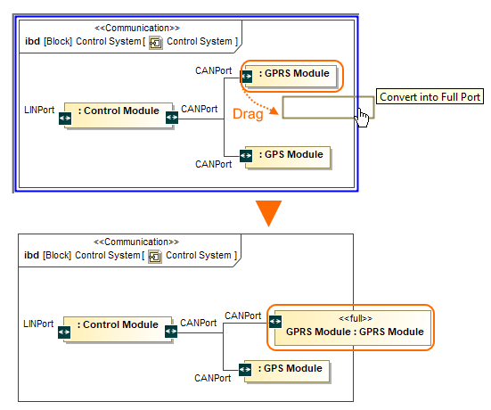
A Full Port is a part on a boundary. You can convert your Parts Properties into Full Ports by dragging them to the diagram frame.
Info
title
Note
All ports, connectors, other information, including the layout will remain unchanged.
To convert a Part Property to the Full Port
Select the Part Property shape and drag it to the diagram frame.
When the diagram frame is highlighted in blue, drop the shape. The Full Port is created on the diagram frame.
Info
title
Note
When the Full Port is created on the diagram frame, you cannot drag it back (except Undo the conversion).
The Part Property converted to the Full Port.
Creating a port while creating a Connector
The procedure below is suitable for all kinds of ports.
To create a port automatically when drawing a Connector from a port to a Part Property
Select a port shape on the diagram pane.
On the smart manipulator toolbar, click and select Part Property shape. appears.
Info
The menu appears if a new port can be created on the Part Property or it has hidden ports.
From the Select Port menu, select one of the following command:
None - if you want to connect Connector straight to the part.
On a port in the list. Hidden ports of the part are listed. The selected port will be represented on the diagram and the connector will be connected to it.
New Port - to create a new port with the same name, type and multiplicity as the port from which the connector is drawn.
New Nested Port - to create a new nested port. Note that the command exists only if the connector is drawn from the nested port.
Info
You can draw a Connector to a port too and the menu appears. As a result, the nested port is created.
The Select Port menu opens after drawing the Connector from the CANPort Port to Part Property typed by GPS Module Block.