Page History
| Content layer | ||||||||||||||||||||||||||||||||||||||||||||||||||||||||||||||||||||||||||||||||||||||||||||||||||||||||||||||||||||||||||||||||||||||||||||||||||||||||||||||||||||||||||||||
|---|---|---|---|---|---|---|---|---|---|---|---|---|---|---|---|---|---|---|---|---|---|---|---|---|---|---|---|---|---|---|---|---|---|---|---|---|---|---|---|---|---|---|---|---|---|---|---|---|---|---|---|---|---|---|---|---|---|---|---|---|---|---|---|---|---|---|---|---|---|---|---|---|---|---|---|---|---|---|---|---|---|---|---|---|---|---|---|---|---|---|---|---|---|---|---|---|---|---|---|---|---|---|---|---|---|---|---|---|---|---|---|---|---|---|---|---|---|---|---|---|---|---|---|---|---|---|---|---|---|---|---|---|---|---|---|---|---|---|---|---|---|---|---|---|---|---|---|---|---|---|---|---|---|---|---|---|---|---|---|---|---|---|---|---|---|---|---|---|---|---|---|---|---|---|
| ||||||||||||||||||||||||||||||||||||||||||||||||||||||||||||||||||||||||||||||||||||||||||||||||||||||||||||||||||||||||||||||||||||||||||||||||||||||||||||||||||||||||||||||
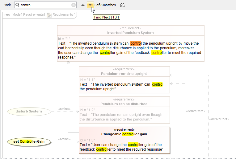
MagicDraw 19.0 provides the ability to search for information in textual information in all types of diagrams, including tables, matrices and maps. Open the search bar by clicking
How to use the Find feature in diagrams and navigate the search results.
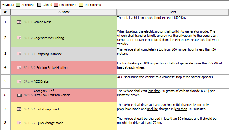
Legends have been improved to allow a wider range of usage options. Now you can:
In this example, a legend is used to adorn Requirement table cells by Requirement status.
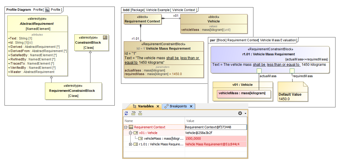
We are proud to announce that our tools will support the new SysML 1.5 specification as of 19.0 LTR! The main change is the new concept of Abstract Requirement, allowing which allows you to extend the Requirement concept and base it on any kind of model elementselement. For an example, download the new Property Based Requirements.mdzip sample model. 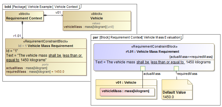
|


| Anchor | ||||
|---|---|---|---|---|
|
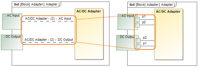
You will be able to represent Association Block usages in the Internal Block Diagrams. Simply drag the Association Block from the model onto a Connector to set it as its type and automatically create a Connector Property symbol with a dashed line attached to the Connector.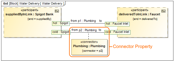
The Plumbing Connector Property is created after dragging the Plumbing Association Block on the p2 Connector.
| Anchor | ||||
|---|---|---|---|---|
|
All new SysML projects use:
- 100x simplified and filtered ISO 80000 library with only 50 hand-picked basic units.
- The new basic US customary, naval and imperial units library (with inch, pound, mile and more).
| Anchor | ||||
|---|---|---|---|---|
|
You can now represent Association Block usages in the Internal Block Diagrams. Simply drag the Association Block from the model onto a Connector to set it as its type and automatically create a Connector Property symbol with a dashed line attached to the Connector.
The Plumbing Connector Property is created after dragging the Plumbing Association Block on the p2 Connector.
| Anchor | ||||
|---|---|---|---|---|
|
The implied Connectors functionality is improved as follows:
- You can select a solid Line Style of the implied relation in the Symbol Properties dialog.
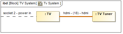
- You can display an implied relation when a Connector is created between a port on one side of the part directly to another part (e.g. the part serves as a communication bus).
| Anchor | ||||
|---|---|---|---|---|
|
When creating a new SysML Allocation Matrix, you can choose Definition or Usage mode. Accordingly, these modes display Allocate relationships either between Activities and Blocks or Actions and Part Properties. By default, the Create SysML Allocation Matrix dialog (see the figure below) appears each time you create a new SysML Allocation Matrix in SysML projects. Differently, when creating a new SysML Allocation Matrix in the MagicGrid project, the usage allocation matrix is created by default. You can change that by specifying the SysML Allocation Matrix Mode option value in the Project Options dialog.
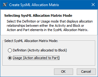
The Create SysML Allocation Matrix dialog.
| Anchor | ||||
|---|---|---|---|---|
|
Cross project refactoring
This feature allows you to move elements from the main project to a used one without losing references. When you work on a project for a long time, it's usual for the project to evolve to the stage when some components tend to get a library type or reusability flavor. A new cross project refactoring feature allows you to simply drag-and-drop selected elements from the main project to a project residing in Project Usages. All of the relationships that the elements have had still remain.
| Anchor | ||||
|---|---|---|---|---|
|
No Magic, Inc. always supports the latest standards. As of this version, MagicDraw supports the new UML 2.5.1 specification! Several minor enhancements include:
- States are redefinable; and
- Executable State Machines (PSSM) are supported
For system engineers, it is also important that the ISO 80000 library is simplified for usability purposes. About 50 of the most useful units are suggested in the list,100x less than introduced earlier. Learn more about updates in basic units >>
| Anchor | ||||
|---|---|---|---|---|
|
- As of 19.0 version, the Document Modeling Plugin is excluded from Cameo Enterprise Architecture product. If you want this plugin to assist for modeling the document structure, you can download free the Document Modeling Plugin and install it.
The Comment path is now displayed after dragging it the Comment element from the Model Browser to the diagram pane when enabling the Display Paths on Element Drop option in the Environment Option dialog. Learn more about displaying paths >>
You can now set the Enable The Automatic Behavior Creation and Type Selection options (renamed to Behavior Creation Mode) and Type Selection Mode buttons now work separately for each project. Learn more about Behavior Creation Mode >> Learn more about Type Selection Mode >>
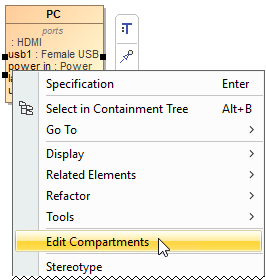
- The Edit Compartments command is now accessible directly from the shortcut menu of the classifier compartments , (such as Properties, Operations, Receptions, Ports, and etc). Learn more about displaying or hiding elements in compartments on shapes >>
- You can now specify the custom column and row query in all matrices, when you need to collect not more than just owned elements. Simply click

") next to Row/Column Scope box in the the Criteria area.A new symbol property allowing you to define the width of a shape frame has been created. Learn more about Criteria area of matrices >>
next to Row/Column Scope box in the the Criteria area.A new symbol property allowing you to define the width of a shape frame has been created. Learn more about Criteria area of matrices >> - Aspect Ratio, a new Diagram Frame symbol property, allows you to choose the appropriate diagram frame format (for example,16:9, A4 Landscape, 4:3 ). Specifying the appropriate diagram frame aspect ratio helps you present diagrams in your PowerPoint or Keynote presentations, PDFs, and so on.
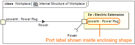
- You are able to specify one more outside label position of a Port. This shows the Port label inside a shape, with the Port created on the shape boundary. Learn how to change the position of port labels >>
- You can choose an existing model element when creating a relation in the relation map. Learn how to decompose an element in the relation map >>
- When creating a new Composite Structure Diagram for a Package, you can specify whether to create a diagram context element automatically or not by selecting an appropriate value for the Diagram Context property in the Project Options dialog. Learn more about Composite Structure Diagram context >>
- As of this version, the Tooltips Style option is located in the Project Options dialog. Learn how to change the tooltips style >>
- You are able to select an additional Show Both or Behavior Name value of the Name Display Mode symbol property for the Call Behavior Action. This allows you to show only the behavior name instead of both if the action name is not specified or the action name matches the behavior name. Learn how to change the name display mode on the Call Behavior Action >>
- When dragging or selecting an image from the Image Library or other resources, you can specify whether to apply an image to the property or to its type in the Project Options dialog > Apply Image To. Learn more about applying images >>
- When specifying a new type for a Activity Parameter Node or Pin in the Activity diagram, you can select the element kind created in the model with a specified name and set as a type.
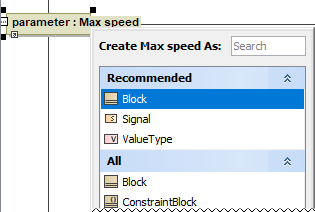
Learn how to specify Pin type >>
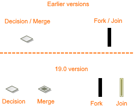
Learn how to specify Activity Parameter Node type >> - The new project option Use different Fork/Join and Decision/Merge notations allows you to draw different notations for the Fork, Join, Decision, and Merge.
- The Note anchored to the diagram frame can now represent the information of the diagram context element (for example, Activity or State Machine). To switch the representation to the diagram information, right-click the Note, and in the shortcut menu clear the selection of Represent Diagram Context.
- You can now define your own documentation server. For that purpose, the new Environment option documentation.server is added to the Path Variables property group. Learn more about working with path variables >>
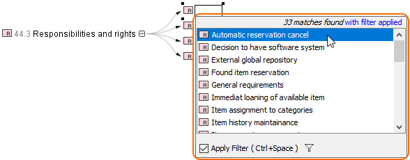
- The filter mechanism includes the following improvements:
- The Exclude Auxiliary Resources replaces the Exclude Used Projects filter option. Learn more about Filter Options >>
- The elements from used projects are included in the search results list by default.
- The new Exclude Auxiliary Resources filter option reduces the search results list by excluding elements contained in auxiliary resources, except elements with the new <<ignoreAuxFilter>> stereotype applied. Learn how to apply stereotype >>
- If you clear the Apply Filter check-box once, your selection is remembered for the next time. - A number of new operations have been added to the built-in operations library.
- Now Mac OS X now supports the mdel:// links and *.mdzip files opening.
- The new documentation layout, including the new home page, is introduced. On the new homepage, you can easily navigate through the menu or simply use the search.
Enhancements in Report Wizard
- You can now include the Attached File element to the main template by using #include, #includeSection, $import.include(), and $import.includeSection(). You can also use the Attached File element as a template of $file.create(), $file.silentCreate(), and $file.createAndWait() to generate reports. Learn more about including documents in generated reports >>
- The DOCX template can now dynamically import the content of other DOCX documents by using $import.include() and $import.includeSection() at runtime, as an alternative to existing RTF, HTML, and text template support. Learn how to import DOCX documents to generate reports >>
- There is now a more convenient, flexible way to generate reports through a command line prompt by specifying element IDs of single or multiple elements in MagicDraw projects as the report scope. Learn more about specifying element IDs via command line prompt >>
- The dialog tool API is now equipped with a select method to create more customized Selection dialog boxes. You can select elements during runtime through the user interface. Learn how to create a customized Selection dialog through Dialog tool API >>
Discontinued Integrations and editions
- The Personal edition is discontinued for all modeling tools.
- For business process modeling, only the Cameo Business Modeler plugin is supported. The development of Cameo Business Modeler tool is discontinued.
- For Cameo Enterprise Architecture, only the Enterprise edition remains. Support of other editions is discontinued. We assure you that the modeling features will not be affected by this change.
- Integration of Eclipse, Rational Application Developer (RAD), openArchitectureWare (oAW), and AndroMDA are no longer supported.
- Development of the Cameo SOA+ plugin is discontinued. However, you will still be able to load projects created in earlier versions with this plugin in your modeling tool. SoaML diagrams are converted to pure UML diagrams and maintenance of the SoaML profile is continued.
Enhancements in Report Wizard
- You can now include the Attached File element to the main template by using #include, #includeSection, $import.include(), and $import.includeSection(). You can also use the Attached File element as a template of $file.create(), $file.silentCreate(), and $file.createAndWait() to generate reports. Learn more about including documents in generated reports >>
- The DOCX template can now dynamically import the content of other DOCX documents by using $import.include() and $import.includeSection() at runtime, as an alternative to existing RTF, HTML, and text template support. Learn how to import DOCX documents to generate reports >>
- There is now a more convenient, flexible way to generate reports through a command line prompt by specifying element IDs of single or multiple elements in MagicDraw projects as the report scope. Learn more about specifying element IDs via command line prompt >>
- The dialog tool API is now equipped with a select method to create more customized Selection dialog boxes. You can select elements during runtime through the user interface. Learn how to create a customized Selection dialog through Dialog tool API >>
| Content block | ||||||
|---|---|---|---|---|---|---|
| ||||||
News of earlier versions |