Page History
...
The FlashLight sample will be used to show how to model a part using an existing UI Configuration. The following steps show you how to create a UI Mockup that represents the entire system parts, which uses only one UI Frame
Open the FlashLight sample, which is located in the
<md.installed><install_root>/samples/simulation directory (FlashingLight.mdzip). The following System Definition Class diagram shows the definition of the FlashLight system. By default, when executing and running this sample, you will see the Button and Light are shown in different Frames.

The following figure demonstrates the runtime User Interface Mockup that represents the Class Button and Class Light

- Right-click the Containment tree and select New Diagram > Other Diagrams > User Interface Modeling Diagram to create a User Interface Modeling diagram.
Create a UI Frame on the UI Modeling diagram by dragging the Class system to the newly created UI Frame as follows

- Create two UI panels in the UI Frame.
Drag the Light property to one of the UI panels to apply the NestedUIConfig stereotype to the UI Panel and set the Light property to the feature tag of that UI panel as follows

Drag an existing UI Configuration named LampBulb to the UI panel that represents the Light property. This will set the dragged UI Configuration to the Config tag of that UI panel as follows

After assigning the LampBulb UI Configuration to the UI panel representing the Light Property, you will see the tagged value Specification of the UI panel that represents the Light property in the Specification of the UI Panel dialog as follows

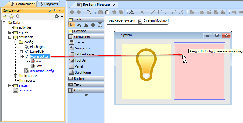
Drag the Button property to another UI panel. Now the UI panel represents the Button property as part of Class system.

Drag an existing UI Configuration named PowerButton to the UI panel that represents the Button property.
Create a new Simulation Configuration element on any Simulation Configuration diagrams; set the simulationTarget tag to Class system and set the UI tag to the UI Frame that represents the Class system.

- Simulate and run the newly created Simulation Configuration. The UI Mockup will appear as illustrated in the following figure
