leased on: January 15, 2015
Easier Ports and Flows Direction Management
The direction of Ports and Flows are now easily identifiable byshowing direction prefixes in the Internal Block Diagram's Model Browser, Specification windows, Compartments and ToolTips.
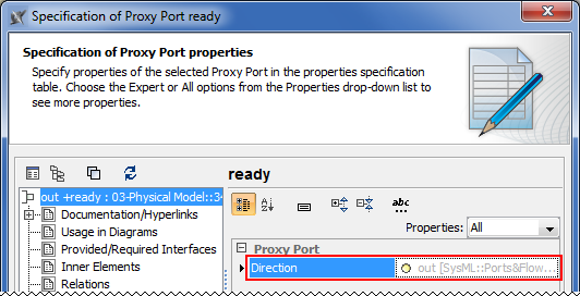
Direction of Proxy Ports
Review all owned and inherited flow properties and directed features of the Proxy Port using new Direction property! You can find it in the Specification window of the Proxy Port.
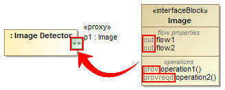
The directed features are not included into combined direction of the Proxy Port by default. To include it set the Include Directed Features into Combined Direction of Proxy Port property value to true in the Project Options dialog.
If all features have direction "out" or "provided", the combined direction is "out". If all features have direction "in" or "required", the combined direction is "in". Otherwise the direction is "inout".
The Direction property is available in tables, matrices, criteria selection dialogs, reports, and open API.
Direction prefixes
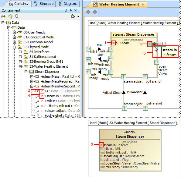
Now directions of flow properties, Proxy and Full Ports can be easily identified in many places with help of direction prefixes.
The flow property direction prefixes are now displayed:
- In compartment area of Part (1). To hide flow property direction prefix on the Part, set the Show Flow Property Direction in Compartment property value to true in the Symbol Properties dialog of that Part.
- In the Model Browser (2).
The Proxy Port direction prefixes are now displayed:
- In compartment area of Block (3). To hide the Proxy Port direction prefixes on the Block, set the Show Proxy Port Direction in Compartment property value to false in the Symbol Properties dialog of that Block.
The Proxy and Full Port direction prefixes are now displayed:
- In the Model Browser (4).
- On the Port shape when its name is displayed inside the shape (5). For this, open the Symbol Properties dialog of the Proxy or Full Port and select Name and Type Labels Inside or All Labels Inside as the Position of Labels property value. To hide the direction prefix on the Port shape, set the Show Direction Prefix Inside Port property value to false in the Symbol Properties dialog of that Port.
- On the ToolTip which opens when you move the pointer over the Proxy or Full Port or its name (6).
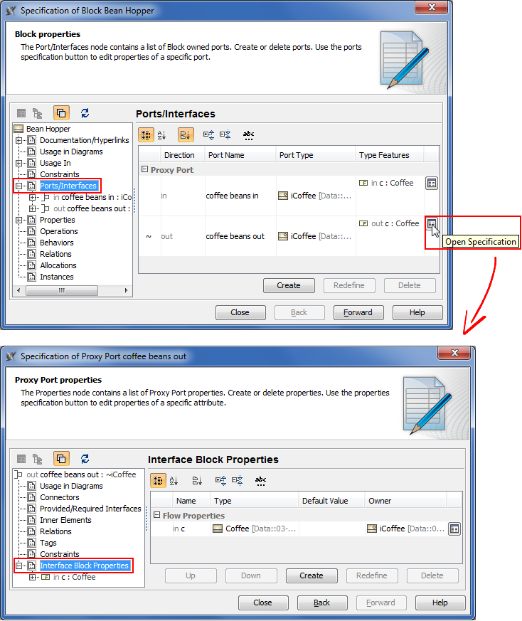
New Ports/ Interfaces property group
All owned and inherited Ports and their Interfaces are now listed in one place! Manage them on the left of the Block Specification window > Ports/Interfaces. For detailed information about selected Port interfaces open its Specification window> Interface Block Properties.
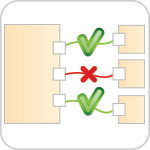
Interface Compatibility Validation
Sophisticated Ports/ Interfaces compatibility checker that instantly detects incorrect connectors in the Internal Block Diagram and suggests solutions.
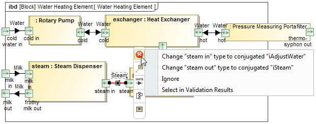
Validation of Ports/Interfaces is more efficient now! It is easier to create the system with compatible connections between Ports because of additional validation of Ports/ Interfaces compatibility rules. They check if:
- Flow is possible
- Flow Properties and directed features match
- Item Flow or Item Property type is compatible with the Interface Flow Property type
Invalid connectors are highlighted in red. Click  on the smart manipulator toolbar and choose one of the suggested solutions.
Traceability Enhancements
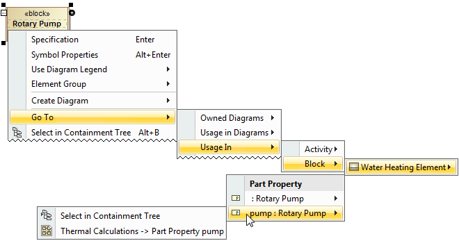
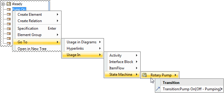
Block or Signal direct and indirect usages are now easily accessible by choosing Go To > Usage In from the shortcut menu of those elements. The Rake Icon is displayed on the shapes for easier navigation into nested structures and diagrams.
Element usage traceability
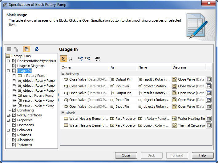
The traceability of the Block, Signal, and Instance elements is much easier now! There are two ways to inspect those element usages in your model:
- For the Block and Signal elements:
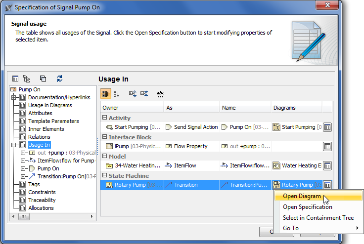
- On the left of the Block or Signal Specification window, click Usage In.
- From shortcut menu of the Block or Signal, choose Go To > Usage In.
- For the Instance element:
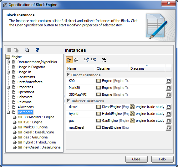
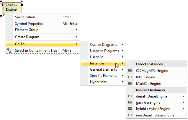
- On the left of the Block Specification window, click Instances.
- From shortcut menu of the Block, choose Go To > Instances.
Block usage traceability
- Part
- Instance
- Partition
- Lifeline
- Reference
Signal usage traceability
You can trace the Signal when it is used:
- In Trigger on Transitions or Accept Event Actions
- As Item Property type
- As Flow Property type
- In Send Signal Action or Broadcast Action
- In Sequence message
Instance usage traceability
Trace all direct and indirect Instances of your Block.
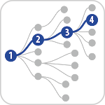
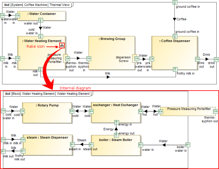
Informative Rake icon
Follow and double-click on the symbol with rake icon for faster navigation in the model! According to the SysML specification, the decomposition of model elements can be represented by the rake icon. It means a reference to a more elaborated diagram.
The rake icon automatically appears on:
- Call Behavior Actions that can refer to another Activity diagram.
- Parts that can refer to another Internal Block diagram.
- Packages that can refer to another Package diagram.
- Constraint Properties that can refer to another Parametric diagram.
- Requirements that can refer to another Requirement diagram.
- Interaction Uses that can refer to another Sequence diagram.
- States that can refer to another State Machine diagram.
- Use cases can that can be realized by other behavior diagrams such as Activity, State Machine or Sequence.
The rake icon is shown by default on the symbol in the new SysML projects. To hide the rake icon set the Show Rake Icon value to false in the Symbol Properties dialog.
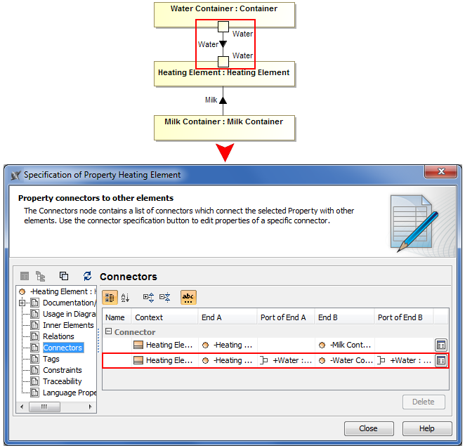
Part connections via Ports traceability
Indirect Part connections via Ports are now collected in the Connectors property group of the Part's Specification window. Inspect the list of connectors and modify their properties.
Editable Relation Maps
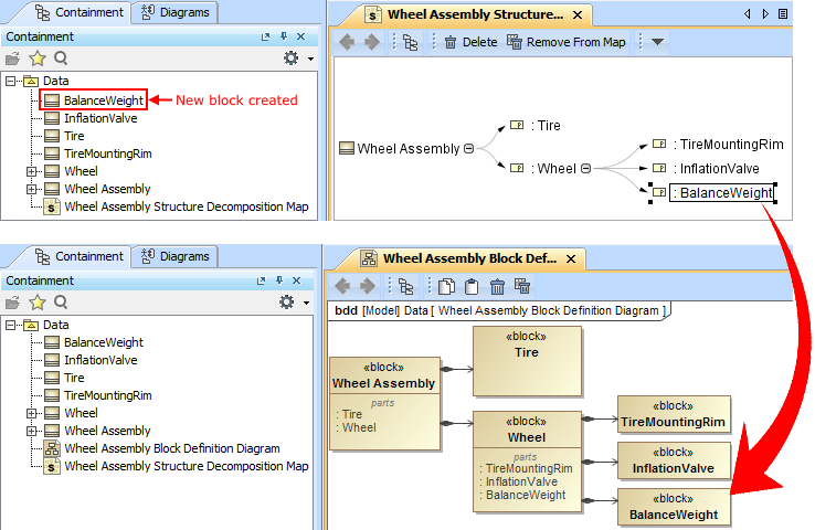
Users can now edit Structure Decomposition and Activity Decomposition maps by directly creating new Blocks and Activities.
Now the Relation Map works like a Mind Map! You can use it not only to browse through a model, but also to create new elements with single click. The Structure Decomposition and Activity Decomposition maps became the fastest model creation tools.
TIP! To create elements faster and more easily:
- Select the element and press Insert (Cmd+I for Mac users) to decompose it.
- Type Part or Action name and press Ctrl+Enter to create the element of the same type.
Easy Transition from Documents to Models
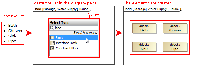
Good news for modelers, who frequently exchange information with project stakeholders that are not modelers and work exclusively with documents! Information exchange becomes easier and faster, because now you can copy listed texts and tables to your MagicDraw model directly from documents, web pages, email messages, presentations, or other text sources.
When you copy a listed text, each item of this list becomes a new named element in your model (to simplify the creation, basic numbering and bullets are not reproduced in the model).
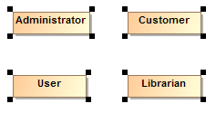
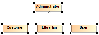
Elements can be created either in the Containment tree or on the diagram pane, as you can see in the following figures.
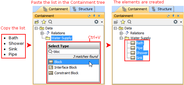
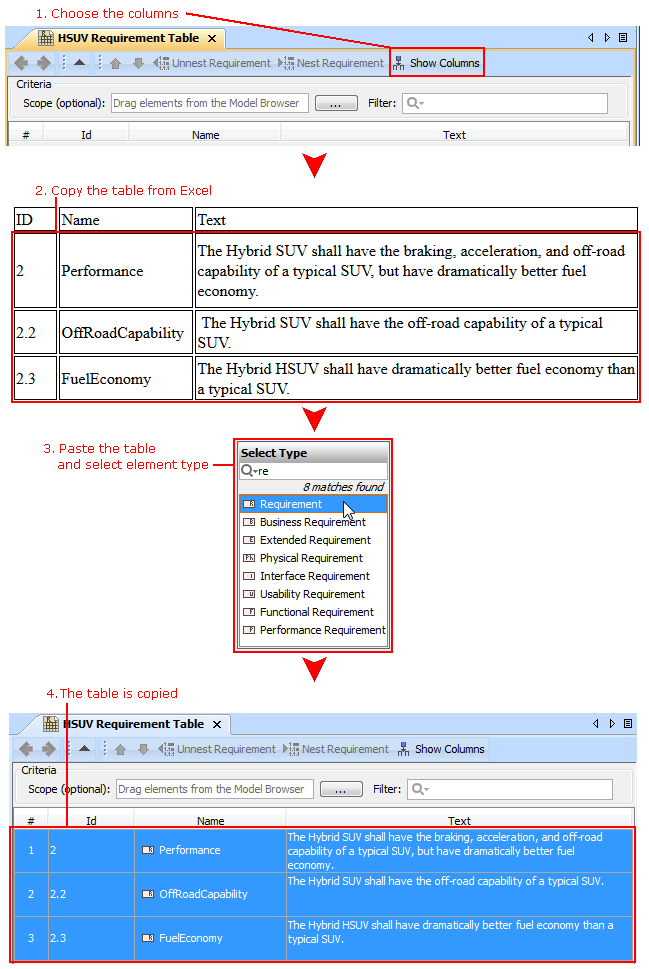
When you copy a table, each row becomes the corresponding element with its properties. If elements already exist in the model, the information updates.

Increased Modeling Efficiency
New property groups in Block Specification window, verdict for Test Cases, smarter diagram layout, simplified search options, more efficient synchronization of elements and their properties, and many more features save modeler's time and allow focusing on what to model, but not how to model and keep the result well-formed.
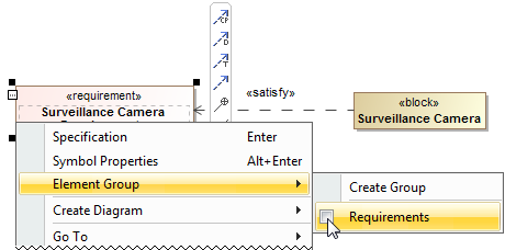
Easy management of element groups
You can create element groups and add or remove group elements quickly and easily.
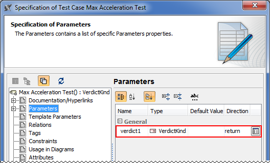
Verdict for Test Cases
When the Test Case is created, its return parameter for the verdict is created automatically.
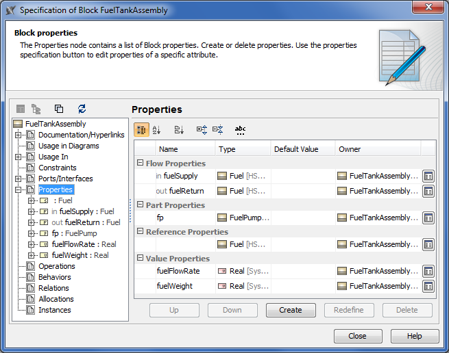
New property groups in Block Specification window
In addition to newly created Usage In, Instances, and Ports/Interfaces property groups, the UML-oriented Attributes property group in the Block Specification window is now replaced with the SysML-oriented Properties property group. All owned and inherited Block properties are grouped as in the Block compartments.
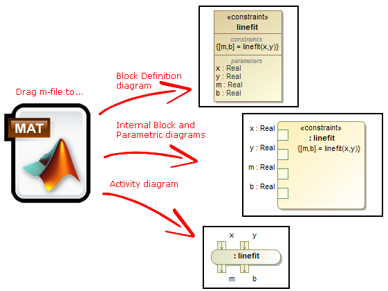
Wrapping MATLAB functions
Integrating custom MATLAB functions into the model is much easier now! Just drag the m-file icon to the diagram to create a Constraint Block, Constraint Property, or Call Behavior Action with corresponding function name and parameters.In earlier versions you could only drag the m-file on existing Constraint Block in Block Definition diagram.
NOTE. M-file must contain function declaration.
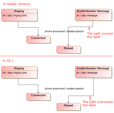
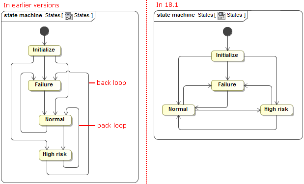
Smarter diagram layout
- When drawing a new path, the layout now overcomes the path labels.
- State Machine diagrams now look better and are easier to read. Plus, the unwanted back loops are eliminated.
- Symbols, created by dragging a group of elements from the Model Browser, are now arranged on the diagram pane as follows:
- In a grid, if there are no paths.
- In the Quick Diagram Layout, if there paths among shapes.
- In a grid, if there are no paths.
Appropriate layouts are applied for displaying parts on a structured classifier shape, if the Layout Parts check box is previously selected in the Display Parts dialog.
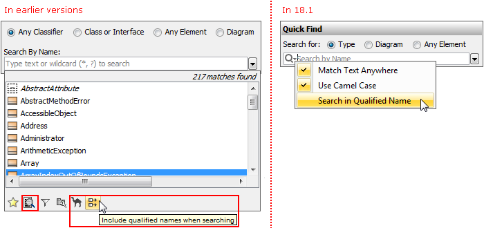
Simplified search options
Changing search options in the Quick Find and Element Selection dialogs as well as in autocompletion lists is now easier and more efficient due to the following changes:
- Search phrase specific options, such as one for turning on/off matching anywhere, are now available on a separate menu. In earlier versions, those options resided together with scope filter options.
- Filter options are now available on the button menu and can be applied on the search scope or removed from it with a single click.
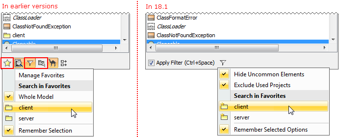
- Options are now commands with meaningful names, but not buttons as in earlier versions. It's now easier to find a desired option.
More efficient synchronization
Keep your model valid and synchronized with your changes! The new synchronizations are introduced and the main element properties are now synchronized. In addition, the solving of the broken synchronization has been enhanced.
- The following elements are now synchronized:
- Attribute of Signal is synchronized with Pin of Send Signal or Pin of Accept Event Action.
- Attribute of Signal is synchronized with Argument of Message.
- Parameter of Behavior is synchronized with Parameter of Signal Reception.
- The following element properties are now synchronized:
- If Pin has no flows connected, Pin direction is converted according to direction specified in Parameter. The same works in the opposite scenario when direction of Parameter changes.
- Pin multiplicity is synchronized according to Parameter multiplicity.
- When a new Activity Parameter Node is created in an Activity, the Activity Parameter Node symbol is automatically represented on the Activity diagram frame.
- When solving the broken synchronization, you can choose the direction of the synchronization. For example, when fixing the synchronization between Parameters (Activity) and Pins (Call Behavior Action) you can select to synchronize in one of the following directions:
- Pins (Call Behavior Action) by Parameters (Activity)
- Parameters (Activity) by Pins (Call Behavior Action)
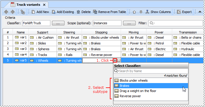
Composite Instances creation in Instance Tables
The Instance table UI was improved to allow easy and fast creation of composite Instances. Just click the Create Instance Specification button  in the slot value cell and create an instance of the slot type instantly or choose from available subtypes.
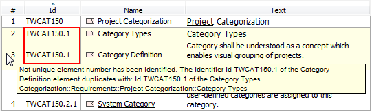
Highlighting of validation rule failures in tables
Now the results of validation rule failures are marked in tables.
- In the Generic Tables, the entire row is marked.
- In the Instance Tables, either a cell, or an entire row is marked. A cell is marked in the case of a faulty slot value. The entire row is marked in the case of a faulty instance.
Projects with File and Report Template Attachments
Do you use hyperlinks to external files in your project? If so, then you must be familiar with the common issues:
- The project references the file, but not its particular version. Hence, as soon as the newer version of this file is committed to your version control system, the project starts referencing inappropriate information.
- If you have a systems specification consisting of a set of models and documents, you need to manually collect the referenced files before giving the entire specification to your peers.
- It takes time to establish a commonly accessible location (e.g., a network drive) where you share hyperlinked files from models to your colleagues.
The latest version of the product includes the solution! Now you can attach any type of file to your project simply by dragging the file icon from the file system to the Model Browser. The particular file version becomes embedded in this project. The contents of the attached file can be modified and the changes are instantly saved to the project.
Attached files can be:
- Hyperlinked from model elements.
- Inserted into rich text format (HTML) and displayed on diagrams (image files only).
- Included in reports.
- Reused in other projects.
Report templates from the local report templates folder can be attached to your project too. For this, use the new functions of the Report Wizard dialog.
Transferring Projects between Consciously Disconnected Environments
Teamwork Servers, which run in consciously disconnected or secured environments, can still exchange projects!
MagicDraw Teamwork Server 18.1 supports transferring project data from one Teamwork Server to another by using any external storage device, such as CD, DVD, hard disc, or flash memory device. The updated version of the shared project can be transferred back to the sharing server and smoothly merged with the original project version. Furthermore, the same project version can be given to several contributors simultaneously, and the contributions to the model they make can be successfully merged as well.
Other News
Conceptual changes in modules
Starting from this version, module is referred as a used project. Keywords "used project" and "project usage" replace the keyword "module" everywhere in MagicDraw UI.
Miscellaneous
- Easily create a Behavior for the Operation. With the new Create Method command on the shortcut menu of the Operation and the Signal Reception, you can create a Behavior (and diagram) faster.
- With the new Display Inner Elements command on the shortcut menu of the State Machine diagram, you can display the shapes of State Machine inner elements faster. The same command is available on the shortcut menu of the Composite State symbol, Activity diagram, and Structured Activity Node symbol.
- Activity diagram created under the Activity now instantly displays all inner elements on this diagram. The same is valid when creating a State Machine diagram under the State Machine.
- Any inherited part can now be quickly redefined directly in the Composite Structure diagrams. Select Refactor > Redefine To, choose a compatible subtype, and let this job be done for you. A new part redefining the original one will be created and graphically replaced in the diagram with all ports and connectors remaining in their places.
- MagicDraw no longer forces the selection of a Metaclass on a Stereotype creation. You can change the Metaclass later from the stereotype's smart manipulator toolbar.
- Selecting a Stereotype or Metaclass no longer requires using the mouse. Use the Up and Down Arrow keys to walk through the lists, press Ctrl+Spacebar to select a desired item, and then press Enter to apply the selected Stereotype or Metaclass.
- Derived properties created using simple navigation operations are now editable.
- The position of text within a shape can be set to the top, center, or bottom by using a new Text Vertical Position property in the Symbol Properties dialog.
- Multiplicity value of an association end can now be edited directly on the diagram pane. Just select the multiplicity area and press F2 to switch it to the edit mode. Then press Ctrl+Spacebar or Ctrl+Backspace to see available suggestions and choose one of them or type a new value.
- Standard and custom subtypes of the selected element type can now be optionally included into search results.
For example, if you need to search for packages as well as for profiles, models, smart packages, and other custom subtypes of the Package, select the new Include Subtypes check box on the Select Element Type dialog after you choose the Package as element type. - Table export to a Microsoft Excel worksheet was improved, and multiline textual values are no longer stripped in the worksheet, if they are stripped in the table - actual, but not displayed data is exported.
- When working with a server project, you can now choose whether to ignore validation rule failures just for you or for all users contributing to that server project.
- Foreign, non-editable projects transferred from other servers can now have domestic, editable branches on the current server.
File format changes
File format reflects changes made in UML metamodel.
Open API changes
More Classes in Open API
The com.nomagic.magicdraw.sysml.util.SysMLUtilities class was added to the open APIs. It provides utility methods for easier work with SysML projects. For more information, see <MagicDraw installation directory>\openapi\docs.
IntelliJ IDEA project for MagicDraw development
An IntelliJ IDEA project with modules for developing two sample plugins was pre-configured and can be found in <MagicDraw 18.1 installation directory>/openapi/ide.
Support
SysML 1.4 support
Now adjunct properties can represent State entry/do/exit behaviors and Transition effect behavior. From the State or Transition shortcut menu, select Tools > Adjunct Property > Create Adjunct Property for <...> to create adjunctProperty representing entry/do/exit behaviors or Transition effect behavior.
UML support
- Optional Port is now identified by the phrase via <port name> in the name string on shapes of the following elements: Call Operation Action, Call Behavior Action, Send Signal Action, Send Object Action, Broadcast Signal Action, and Start Object Behavior Action.
- Body of an Opaque Behavior can now be optionally displayed instead of its name on the State or Transition shape, when this Opaque Behavior is used as Entry/Exit/Do Behavior of State or Effect of Transition.
UML metamodel related changes
- Removed associations:
- parameter between ValueSpecification and Parameter
- parameter between Pin and Parameter
- Added associations:
- syncElement between two Elements
- Removed associations:
Fixed Issues
You can check the following lists of publicly available or your own reported issues fixed in version 18.1 FR:
Note: You will be required to login. Use same credentials as to your account.