This functionality allows you to visualize relationships that are created between elements in the model, but are not displayed on the diagram pane. There are two options to display paths among the element shapes:


To display paths between selected element shapes


  1. On a diagram pane, select two or more elements.

  2. Do one of the following:
    • Right-click to open the shortcut menu, and select Display > Display In-Between Paths.
    • On the diagram toolbar, click Display and select Display In-Between Paths.
    • On the main menu, click the Analyze > Display In-Between Paths.

      The Display In-Between Paths command is available only when two or more shapes are selected.

The existing paths between selected element shapes are displayed on the diagram pane. 

The paths won't be displayed if:
       - The selected shape doesn't have any relationships with the shapes displayed on the diagram.
       - All paths are already displayed on the diagram pane.
Paths to self also will not be displayed.


To display all existing paths of the selected shape


  1. On a diagram pane, select one or more elements.
  2. Do one of the following:
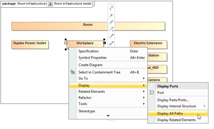
      • Right-click to open the shortcut menu, and select Display > Display All Paths.
      • On the diagram toolbar, click Display and select Display All Paths.
      • On the main menu, click the Analyze > Display All Paths.
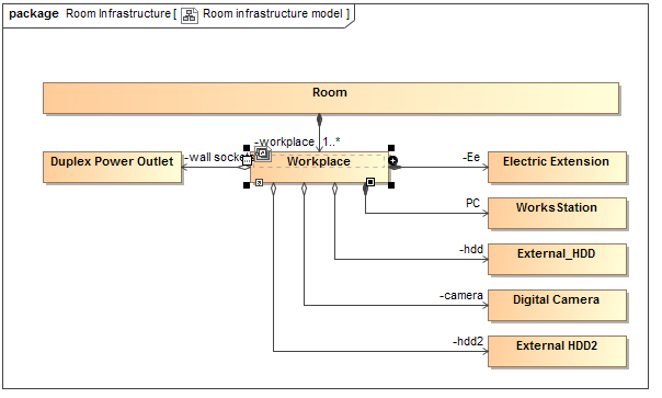
    All the existing paths among the selected shape and other shapes on the diagram pane are displayed. If the element has a path to self, this path will be displayed as well.


This example presents the workflow on representing the paths between shapes on the diagram pane when they are already created in the model.

The Class shapes without any paths between them are represented in the Room infrastructure model Class diagram. In this case, paths between those classes exist in the Containment tree under the Relations node (see the figure below).
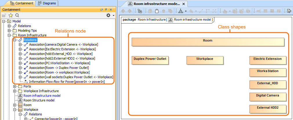
If you want to visualize how the Workplace Class is related with other shapes displayed on the diagram pane, you can do so easily by using the Display All Paths command. One way to reach this command is from the shortcut menu of the selected shape (see the figure below).
After selecting the Display All Paths command, all paths between the Workplace Class and other shapes on the diagram pane are displayed (see the figure below). The diagram shows that the Room consists of between one and an arbitrary number of Workplaces. The Workplace consists of Electric Extension and Works Station. Also, the Workplace can contain Duplex Power Outlet, External HDD2, Digital Camera, and External_HDD.

To display paths among element shapes automatically when displaying elements


  1. On the main menu, select Options > Environment.
  2. In the Environment Options dialog, find the Display Paths on Element Drop option and set it's value to true.
  3. Click OK.
  4. Select the elements in the Model Browser and drag them on the diagram pane.

    The shapes and paths between them are displayed.

    The paths won't be displayed if:
           - The selected shape doesn't have any relationships with the shapes displayed on the diagram.
           - All paths are already displayed on the diagram pane.

Related pages

Related page in Developer Guide


Sample model

The model used in the figures of this page is the Composite structure diagram sample model. To open this sample do one of the following: