Displaying simulation information
During simulation, views can display runtime information associated with model elements. This information is dynamically updated during the simulation and reflects the current state of the simulated system. Observing runtime values, execution indicators, and requirement statuses directly on views makes it easier to understand how the system evolves over time.
Simulation annotations in views
During simulation, behavior concepts (e.g., states) or ports and connections (e.g., payloads flowing through connections) displayed in views are annotated to indicate the execution flow.
Simulation annotations are displayed for a state when a State Usage is placed inside a Part Usage in a view and that view is located within the Root Simulation Target hierarchy.
If the view displays the Root Simulation Target, the view does not need to be located within the Root Simulation Target hierarchy and may be placed anywhere while still displaying the simulation annotations.
Simulation annotations mark symbols as:
- Active (default color
 ) - the symbol that is currently being executed during the simulation.
 - Visited (default color
 ) - the symbols that have already been executed.
 - Last Visited (default color
 )- the symbol that has been executed most recently.
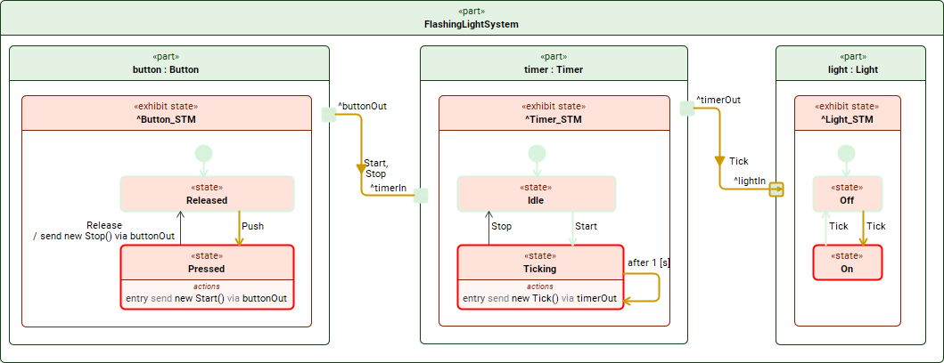
Annotations of the flashlight system simulation
Configuring annotation colors
To change the colors used for simulation annotations
- In the main menu, select Options > Project.
- In the Project Options dialog, select the Simulation option group.
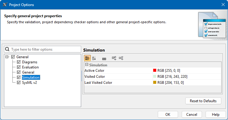
- On the right side of the dialog, select the value cell you want to change and click
 .
. - In the open dialog, select a new color and click OK.
- Click OK to close the Project Options dialog.
Displaying runtime values
In views, runtime values are displayed in blue. During simulation, these runtime values replace the default values and are displayed next to:
- Attributes
- References
- Satisfy requirements
Attributes or references that contain expressions may display calculated values during simulation. These values appear directly in the view near the element names and update continuously as the simulation progresses.
When a simulation is running, views do not display types; only the current runtime values are shown. This reduces visual complexity and improves view readability during execution.
You can also modify runtime values directly in views and change simulation results in real-time.
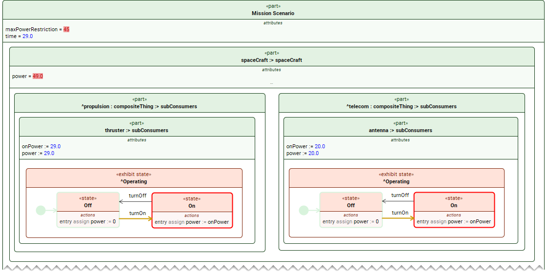
A sample view displaying runtime values during model simulation.
Supported data types
Runtime values can be displayed in views only for the following data types:
- Primitive:
- Integer
- Real
- Boolean
- String
- Enumeration
If a property has a different data type, its runtime value is not displayed directly in the view.
Resizing shapes to fit runtime values
If a runtime value does not fit inside a shape and is cut off, resize the shape as described below:
- Select the shape you want to resize.
- Do one of the following:
- Click
 on the shape.
 - Click
 in the view toolbar.
- Click
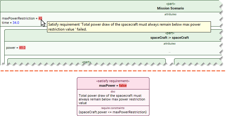
Automated requirement verification
Model simulation supports automated requirement verification. Runtime values on part, attribute, and reference shapes are highlighted in green or red to indicate whether the related requirement is satisfied. The verification result on the satisfy requirement shape is also highlighted in green or red, respectively.
In addition, a tooltip containing the text of the unsatisfied requirement appears when you hover the mouse pointer over a failing part, attribute, reference, or satisfy requirement shape.