Now that you have created the StopWatch Class, next create a State Machine to be its classifier behavior. This State Machine defines the active behavior of a StopWatch, which may be executed using Cameo SImulation Toolkit.
To define the State Machine for the StopWatch class
- Right click on the StopWatch symbol on the Class diagram and select Create Diagram > State Machine Diagram. A new State Machine element will be created under the StopWatch class with a new State Machine diagram.
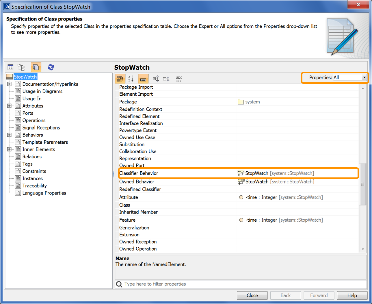
- Make sure that the StopWatch state machine is the classifier behavior of the StopWatch class. To see the classifier behavior of the StopWatch class, right click on the StopWatch symbol in the Model Browser and select Specification from the context menu. The Specification window will open.
Select All from the Properties drop-down menu (see the following figure).
- Scroll down to see the Classifier Behavior row and you will see that the classifier behavior of the StopWatch Class is defined by the StopWatch State Machine (see the following figure). (If it is not, then click on the Classifier Behavior property and choose the StopWatch State Machine to be the classifier behavior.)
Now create the States and Transitions for the StopWatch State Machine.
To add the ready, running, paused, and stopped States
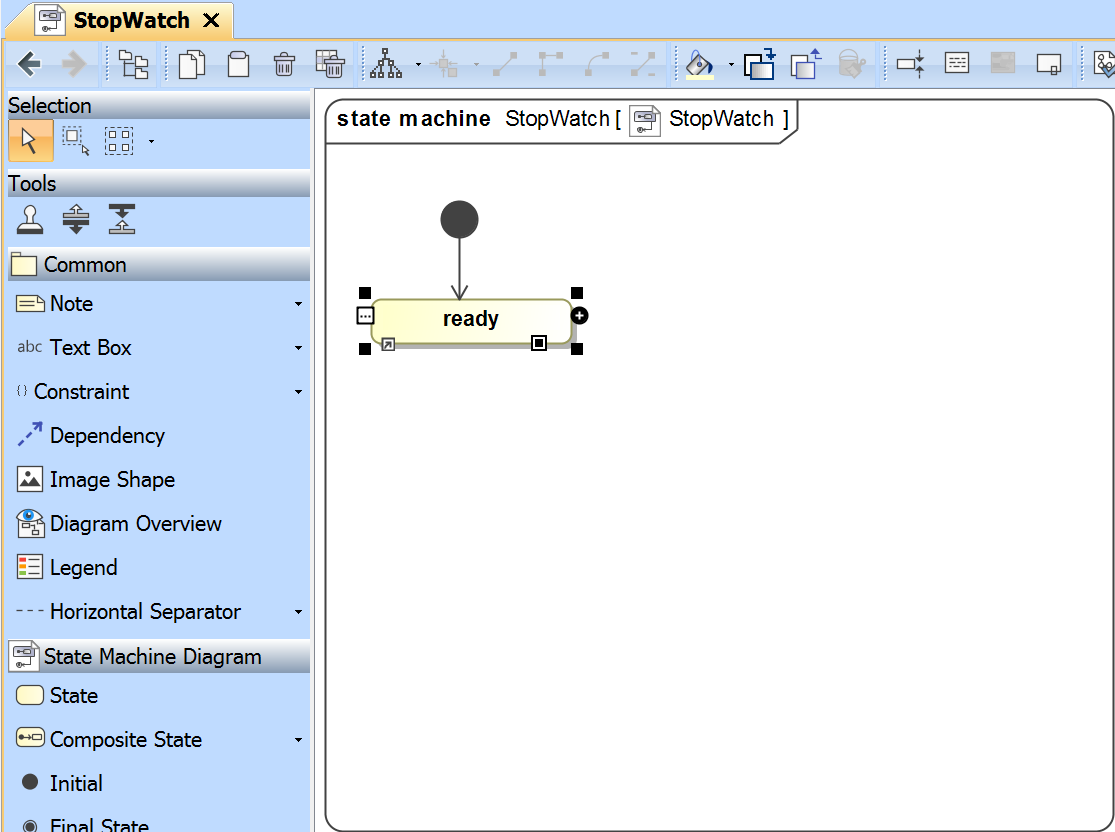
The State Machine diagram is automatically created with an initial Pseudostate having a Transition to a starting State. Name the starting State ready (see the following figure).
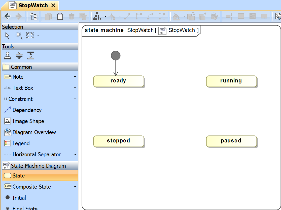
- Click State on the State Machine Diagram toolbar, and then click any area on the diagram to place a State. Name the created State running (see the following figure).
- Repeat Step 2 to create the paused, and stopped states.
To add a Final State to the State Machine diagram
- Click Final State on the State Machine Diagram toolbar, and then click any area on the diagram to place the Final State (see the following figure).

Next you need to add Transitions between the States on the State Machine diagram.
To add Transitions to the State Machine diagram
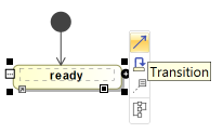
- Click on a State (e.g., the ready state) that will be the source of the Transition to be created. The smart manipulator toolbar will open (see the following figure).
Click the Transition icon on the smart manipulator toolbar (see the following figure).
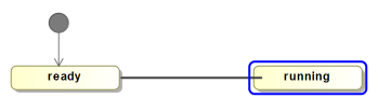
Click a State (e.g., the running State) that will be the target of the Transition (see the following figure).
- Repeat Steps 1 to 3 to create more transitions between the following states (see the following figure):
from the running State to the paused State
from the running State to the stopped State
from the paused State to the running State
from the paused State to the stopped State
from the stopped State to the ready State
from the stopped State to the final State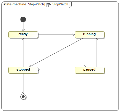
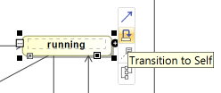
- Create a looping transition to the running state by clicking the Transition to Self icon on the smart manipulator toolbar (see the following figure).
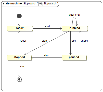
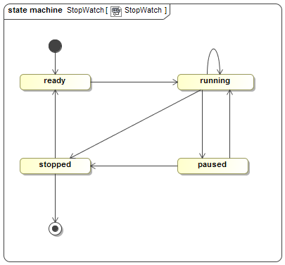
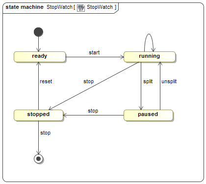
- Now your StopWatch State Machine diagram will look similar to the the following figure.
Some of the Transitions just created will have Signal Event triggers. These triggers reference Signal elements, which will be stored in a separate Package. You can add a Package and create the Signal elements by using the Model Browser context menu.
To add a new Package for the Signal elements
- Right click on the Model node in the Model Browser and select Create Element > Package.
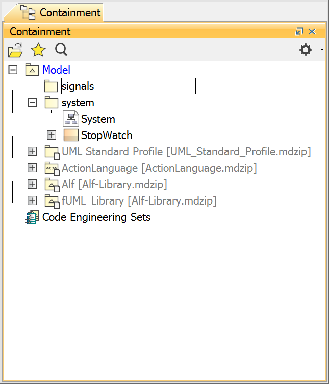
- Name the created Package signals (see the following figure).
To create Signal elements
- Right click on the signals Package and select Create Element > Signal. (If you don't see an entry for Signal, click on Expert in the lower left-hand corner of the Create Element window.)
- Name the created Signal reset. The reset Signal will be created and stored in the signals Package.
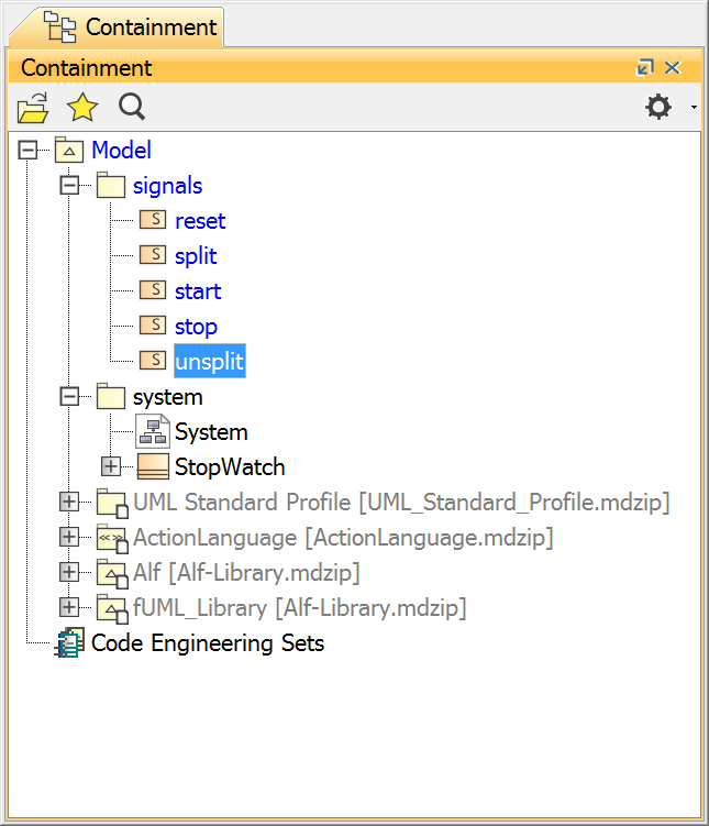
- Repeat steps 1 and 2 to create the split, start, stop, and unsplit Signal elements (see the following figure).
To create Signal Events for the Transitions on the StopWatch State Machine diagram
- Drag a signal element from the Model Browser to a transition on the State Machine diagram (see the following figure). The Signal Event will later be specified as the trigger of the Transition.
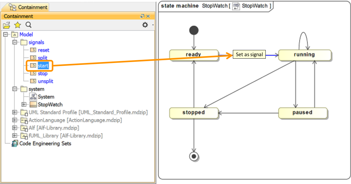
To create a Signal Event for each Transition (see the following figure)
- Drag the start Signal to the Transition between the ready and running States.
- Drag the split Signal to the Transition between the running and paused States.
- Drag the stop Signal to the Transition between the running and stopped States.
- Drag the unsplit Signal to the Transition between the paused and running States.
- Drag the stop Signal to the Transition between the paused and stopped States.
- Drag the reset Signal to the Transition between the stopped and ready States.
- Drag the stop Signal to the Transition between the stopped and final States.
Now each and every Transition between the States has its own Signal Event. Next, you will also need to create a Time Event for the Transition to Self of the running State.
To create a Time Event for the Transition to Self of the running state
- Right click the Transition to Self of the running state and select Specification to open its Specification window.
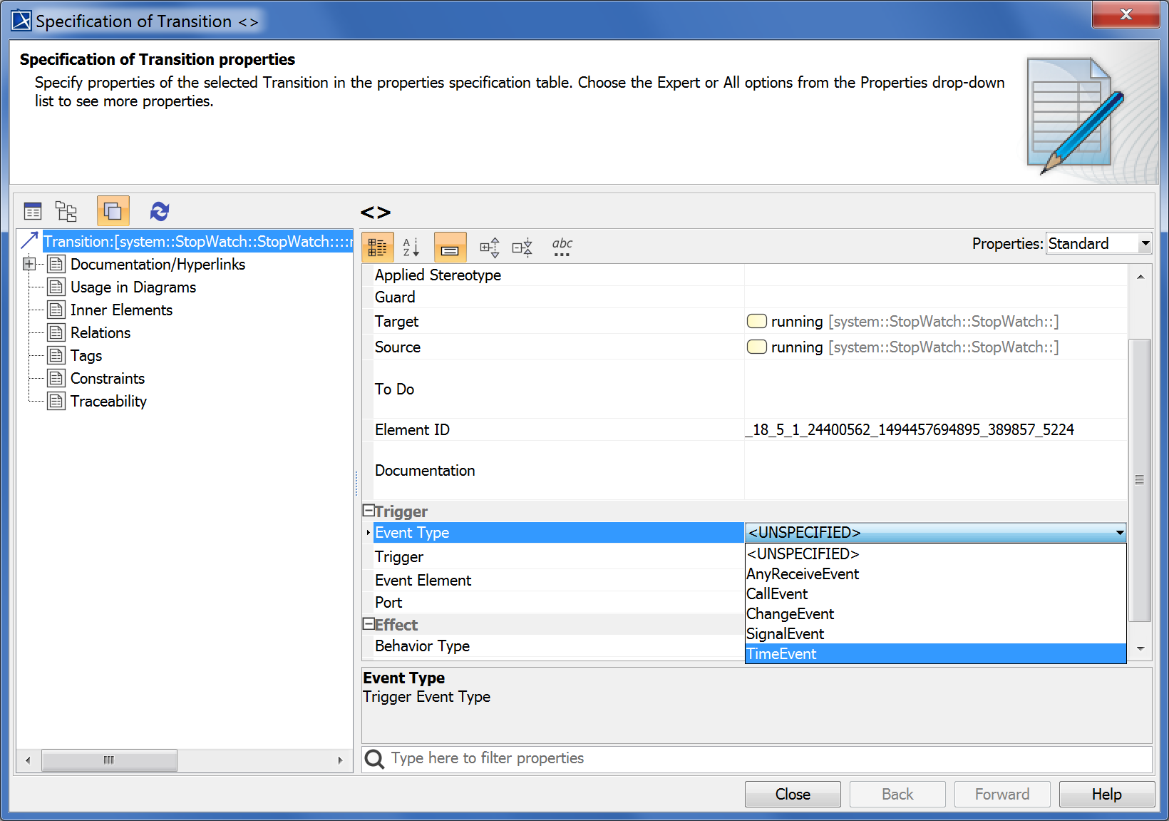
- Click the Categorized View button to open the properties of the transition in the categorized view (see the following figure).
- Click the Event Type row in the Trigger category and select TimeEvent from the drop-down menu (see the following figure).
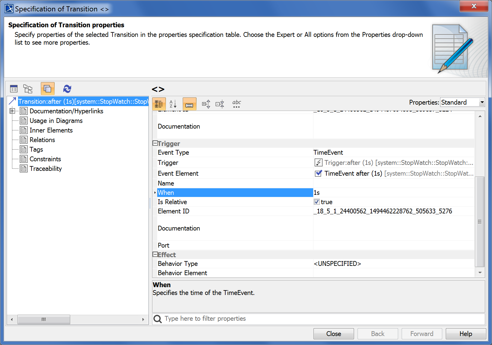
- Click the When row in the Trigger category and type "1s" to specify that the Time Event will occur every second (see the following figure).
- Check the Is Relative box, so it is true (see the following figure).
- Click Close. Your State Machine should look similar to the following figure.