On this page
UML to SQL (Generic / Oracle) transformation is based on the same copy mechanism as the other transformations are. It copies the source model part to the destination (unless the in-place transformation is performed), remaps types, and then performs model reorganization to turn the model into an SQL model.
To transform a UML model to SQL
- Open the UML model you want to transform or create a new one.
- Open the Model Transformation Wizard. Do one of the following.
- On the main menu, click Tools > Model Transformations.
- Select the package in the Model Browser and click Tools > Transform on its shortcut menu.
3. Perform the steps of the wizard.
3.1 Select the transformation type.
3.2 Select the transformation source and specify the location wherein the output should be placed. If you open the wizard from the shortcut menu of a package, this package and all its content will be automatically selected as the source.
3.3 Check type mappings. You can select the transformation type map profile in this step.
3.4 Specify transformation details.
4. Click Finish when you are done.
Conversion of classes
UML classes from the source model are converted into tables.
Each property of the source class becomes a column in the result table. If a property in the UML model had the explicit multiplicity specified, nullable=true (for [0..1] multiplicity in source property) and nullable=false (for [1] multiplicity in source property) marking is applied on result columns.
Operations contained in the source class are not copied into the result table.
Primary keys autogeneration
If a UML class in the source model had no primary key (it is declared by applying an appropriate stereotype), an ID column is generated and marked as the primary key (PK).
Tip
You can turn off the automatic generation of PKs during the model transformation. For this, click to clear the Autogenerate PK check box in the Transformation Details pane (the 4th step of the Model Transformation Wizard)
In this case, you must specify PKs and FKs manually after the model transformation.
The Autogenerated PK name template transformation property governs the name of the generated ID column. The %t pattern in the name template is expanded to the current table name.
The Autogenerated PK type transformation property determines the type of the ID column. The default type is integer.
Sequence autogeneration
Note
This feature is only available in UML to SQL (Oracle) transformations. Generic SQL models do not have sequence support yet.
For each single-column PK in the destination a sequence object can be generated.
The Autogenerate Sequences transformation property governs the sequence autogeneration. Possible choices for setting the property value are as follows.
- Do not generate sequences choice switches sequence generation off.
- Generate sequences for all single-column PKs choice switches sequence generation on.
- Generate sequences for all autogenerated PKs choice switches sequence generation on but only for those PKs that there automatically generated by the tool (but not for PKs which were declared by the user).
Conversion of associations
One-to-one and one-to-many associations between classes in the source UML model are converted to foreign key relationships and to foreign key columns in the table, which is at the multiple end.
The Autogenerated FK column name template transformation property governs the name of the generated FK column. A name template can use the following patterns.
- %t is replaced by the name of the table, the foreign key is pointing to.
- %k is replaced by the key name, this foreign key is pointing to.
- %r is replaced by the name of the relationship role, which is realized by this foreign key.
Note that the type of the FK column matches the type of the PK column, to which this key is pointing.
Many-to-Many associations are transformed into the intermediate table. An intermediate table is generated for an association and has two FK relationships pointing to the tables at association ends. FK are generated in the same way as for one-to-many associations.
The Autogenerated table name template transformation property governs the name of the generated intermediate table (%t1 and %t2 are replaced by the names of the tables at relationship ends).
You can create your own Autogenerated FK constraint name template. It makes easier to find FKs in the generated code. Also, it is helpful if you have some naming convention at your company.
You can use the same described patterns to specify the FK name template. For example, if you define the FK constraint name template as “fk_%r”, appropriate relations in the model will look like it is depicted in the following figure.
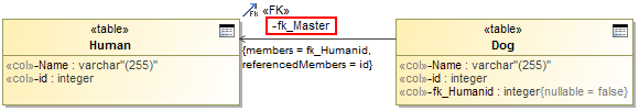 Example of transformation when FK name template is used.
The same sample in the, for example, SQL code will look as follows.
CREATE SEQUENCE pets.Dog_SEQ;
CREATE SEQUENCE pets.Human_SEQ;
CREATE TABLE pets.Human
(
	Name varchar (255),
	id integer,
	PRIMARY KEY(id)
);
CREATE TABLE pets.Dog
(
	Name varchar (255),
	id integer,
	fk_Humanid integer NOT NULL,
	PRIMARY KEY(id),
	CONSTRAINT fk_Master FOREIGN KEY(fk_Humanid) REFERENCES pets.Human (id)
);
To create the FK constraint name template
- In the Transformation Details (the 4th step of the Model Transformation Wizard), click the Autogenerated FK constraint name template specification cell. The Edit button appears.
- Click the Edit button and, in the opened Autogenerated FK constraint name template dialog, define the FK name template. You can use specific names and patterns, such as %t (a table name) or %r (a relationship role) in the name template definition.
- Click OK when you are done and continue the transformation setup process.
Conversion of identifying associations
Some relationships in the source model are treated as identifying relationships. In case of identifying a relationship, the objects of the class, which is at the multiple end of the association, are not independent, that is, they can exist only in association with the objects at the singular end of the association. In the resulting SQL model, the FK of these relationships is included into the PK of the table.
The PK of the dependent table is composite and contains the following two columns as a result.
- ID column of the table
- FK to the independent table
Unfortunately, UML models lack model data and notation to specify, which associations are identified. Hence transformation has to guess this. It uses the following heuristics - the composite associations are treated as identifying, while the other associations are not.
The Treat composition relationships as identifying transformation property governs these heuristics. If this property set to false, all associations are treated as not identifying.
Conversion of multivalued properties
In UML models, properties can be multi-valued (e.g. [0..7], [2..*]). However, in databases columns they can be only single-valued. Transformation uses two strategies to handle multi-valued properties in the source model.
If the upper multiplicity limit is small and fixed, e.g., [0..3], then columns are simply multiplied the necessary number of times. The result table will have multiple columns with sequence numbers appended to their names (like “phone1”, “phone2”, and “phone3” columns in the result for a single phone[0..3] property in the source).
The Max Duplicated Columns transformation property governs the maximum number of columns, that are generated using this strategy.
If the upper multiplicity upper bound is larger than this limit or unlimited, then an auxiliary value table is generated for such multi-valued properties. This table is FK-related to the main table of the class, and holds a “value” column for storing property values.
The Value table name transformation property governs the name of the generated table (%t in this property is replaced by the name of the table and %r - by the property name). So, the table name template “%t_%r_VALUES” gives a “Person_Phone_VALUES” table name for the Person::phone property).
Conversion of generalizations
In UML, generalizations are used extensively, while SQL domain lacks the concept of generalizations. Hence during the transformation, generalization trees are transformed into different concepts to simulate the generalization approximately.
There are three different strategies for simulating generalizations in the result domain as follows.
- Multiple Tables, Decomposed Object strategy.
- Multiple Tables, Copy Down strategy.
- One Table, Merged strategy.
Specify the strategy for converting generalization trees in the Generalization Tree transformation strategy transformation property.
Multiple tables, decomposed object strategy
This strategy consists of the following actions.
- Each class is converted to a separate table.
- Direct (not inherited) properties of the class are converted to the columns of the table.
- A foreign key to the table of the base class is created. The table of the base class carries the inherited columns.
- Primary keys of all the classes participating in a hierarchy tree are the same (there can be several hierarchy trees in the same transformation source, and each one is handled separately). PK of the specific tables is also an FK to the parent table.
This strategy is the closest one to UML and fits nicely from theoretical standpoint since there is no data duplication. The only problem of this approach is the performance of data retrieval and storage. During the storing operation, objects are decomposed into several parts, each stored in a different table (that is why the strategy is called Decomposed Object strategy), and for retrieving the object you have to query several tables (with resulting multi-level joins).
Multiple tables, Copy Down strategy
This strategy consists of the following actions.
- Each class is converted to a separate table.
- The table of each class holds columns for properties of that class AND all the columns, copied from the base class (that is why this strategy is called Copy Down strategy).
As a result each table possesses the complete column set to carry data about an object of particular type. All the data of the object is stored in one table.
The weak point of this strategy is that the association relationships between tables are copied down also. Hence each association in the source can produce many foreign keys in the target. Writing SQL queries against this database layout is not very convenient. Also, if you want to retrieve all the objects of the particular class, you have to query several tables and union the results.
One table, merged strategy
This strategy consists of the following actions.
- All the classes in the generalization hierarchy are folded into one large table.
- All the properties of all the classes become table columns (note that columns that were mandatory in the specific classes become optional in the merged table).
- A separate selector column is generated, which indicates the type of the object carried by the particular line.
The Selector Column Name, Selector Column Type and Selector Column Type Modifier transformation properties determine the selector column format.
This strategy is suitable for very small hierarchies usually of just one hierarchy level with a couple of specialization classes, each adding a small number of properties to the base class. E.g., general class “VehicleRegistration” and a couple of subclasses: “CarRegistration” and “TruckRegistration”.
This strategy suites simple cases well. It is simple and fast. However, it does not scale for larger hierarchies and produces sparse tables (tables with many null values in the unused columns) in this case.
Conclusions and future improvements
Note that all hierarchies from the transformation source are converted using the same method. You cannot choose different strategies for each particular case of the generalization tree. This is considered as a future improvement for the transformations.
Conversion of DataTypes
You can choose two strategies to transform datatype of data to SQL as follows:
- To transform datatypes to structured user defined types. This is a default case.
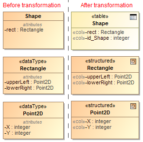 Example of datatype transformation to structured user defined types.
The same sample in the Oracle SQL code will look as follows.
CREATE SEQUENCE Shapes.Shape_SEQ;
CREATE OR REPLACE TYPE Shapes.integer AS OBJECT NOT FINAL INSTANTIABLE;
/
CREATE OR REPLACE TYPE Shapes.Point2D AS OBJECT
	(
	X integer,
	Y integer
	) NOT FINAL INSTANTIABLE;
/
CREATE OR REPLACE TYPE Shapes.Rectangle AS OBJECT
	(
	upperLeft Point2D,
	lowerRight Point2D
	) NOT FINAL INSTANTIABLE;
/
CREATE TABLE Shapes.Shape
(
	rect Rectangle,
	id integer,
	PRIMARY KEY(id)
);
- To expand datatypes into separate columns at the point of usage. Each property of a class having a datatype as a type is expanded into a set of columns—one column per each attribute of the datatype (including inherited attributes). Column types are copied from the source datatype attribute types (modulo the transformation type mapping). If the original datatype attribute is multivalued, the resulting column is further modified in the same manner as multivalued class attributes. The datatype expansion is recursive.
 Example of DataType transformation to separate columns.
The same sample in the Oracle SQL code will look as follows.
CREATE TABLE Shapes.Shape
(
	X_upperLeft_rect integer,
	Y_upperLeft_rect integer,
	X_lowerRight_rect integer,
	Y_lowerRight_rect integer,
	id integer,
	PRIMARY KEY(id)
);
On the conversion of DataTypes into separate columns at the point of usage, you can define names of the columns. By default, the format “%r_%a” is used, where %r is a name of a class attribute and %a is a name of a DataType attribute. In the example depicted in the preceding figure, column names are constructed according to the default template, like rect_upperLeft_X, rect_lowerRight_Y and so on.
To select a strategy for the DataType transformation
- In the Transformation Details (the 4th step of the Model Transformation Wizard), set the Expand datatypes value to
- False to transform datatypes to structured user defined types.
- True to expand datatypes into separate columns at the point of usage
2. Continue the transformation setup process.
To define a template name for columns
- In the Transformation Details (the 4th step of the Model Transformation Wizard), click the Expanded datatype column name template specification cell. The Edit button appears.
- Click the Edit button and, in the opened Expanded datatype column name template dialog, define the column name. In the column name definition, you can use specific convenient names and the following patterns.
- %r - a name of a class attribute
- %a - a name of a datatype attribute
- %t - a name of table
3. Click OK when you are done and continue the transformation setup process.
The column name template is defined in the Expanded datatype column name template property.
Conversion of enumerations
When transforming enumerations, you can choose two following strategies:
• To transform the enumeration to check constraints at the point of usage. This is the default case. Every class attribute of the enumeration type in the transformation source is transformed to the table column of a char type.
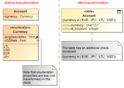 Example of enumeration transformation to check constraints.
The same sample in the SQL code will look as follows.
CREATE TABLE Enumeration_CheckConstraint.Account
(
	currency char (3),
	id_Account integer,
	CHECK(currency in ('EUR', 'JPY', 'LTL', 'USD')),
	PRIMARY KEY(id_Account)
);
To transform enumerations to lookup tables. This strategy can handle the more complex enumerations, for example, enumerations having their own attributes. The lookup table is automatically populated with enumeration literal values, and INSERT statements are generated during the SQL code generation. For each attribute that enumeration source has (including inherited attributes) the column in the target table is created. Attributes are transformed using the normal transformation rules for class attributes (including the type mapping, data type expansion, if requested, and multivalue-attribute expansion). The name column is added to the lookup table and the primary key is automatically generated (see Primary keys autogeneration). Every class attribute of the enumeration type in the transformation source is transformed to the foreign key.
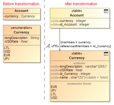 Example of enumeration transformation to lookup tables.
The same sample in the SQL code will look as follows.
CREATE TABLE Enumeration_LookupTables.Currency
(
	longDescription varchar (255),
	USDRate,
	id_Currency integer,
	name char (3) NOT NULL,
	PRIMARY KEY(id_Currency)
);
INSERT INTO Enumeration_LookupTables.Currency(id_Currency, name) VALUES(0, 'EUR');
INSERT INTO Enumeration_LookupTables.Currency(id_Currency, name) VALUES(1, 'JPY');
INSERT INTO Enumeration_LookupTables.Currency(id_Currency, name) VALUES(2, 'LTL');
INSERT INTO Enumeration_LookupTables.Currency(id_Currency, name) VALUES(3, 'USD');

CREATE SEQUENCE Enumeration_LookupTables.Currency_SEQ;

CREATE SEQUENCE Enumeration_LookupTables.Account_SEQ;

CREATE TABLE Enumeration_LookupTables.Account
(
	currency integer,
	id_Account integer,
	PRIMARY KEY(id_Account),
	FOREIGN KEY(currency) REFERENCES Enumeration_LookupTables.Currency
(id_Currency)
);
To select a strategy for the Enumeration transformation
- In the Transformation Details (the 4th step of the Model Transformation Wizard), click the Enumeration transformation strategy specification cell. The list of available strategies appears. Select one of the following.
- Check Constraints to transform the enumeration to check constraints at the point of usage.
- Lookup Table to transform enumeration to lookup tables.
2. Continue the transformation setup process.
Package hierarchy reorganization
UML models usually have a moderately deep package nesting organization, while SQL models can have at most one package level - the schemas. Hence during the transformation, packages should be reorganized.
The Change package hierarchy transformation property governs the package reorganization. Possible choices for setting the property value are as follows.
- Leave intact choice switches reorganization off.
- Flatten packages choice forces flattening of the packages of the source, leaving only the top level packages in the destination.
- Strip packages choice removes all packages of the source.
Naming of transformed elements
While transforming your UML models to SQL, you can modify names of the transformed elements according to given naming rules. There are several predefined rules as follows.
- Replace spaces or special characters in the element name with the underscore sign “_”. For example, the name in source “Customer Profile” and “Terms&Conditions” could be transformed as “Customer_Profile” and “Terms_Conditions” accordingly.
- Capitalize element names after the transformation. For example, the name in source “Customer” could be transformed as “CUSTOMER”.
- Pluralize element names after transformation. For example, the name in source “Customer” could be transformed as “Customers”.
- Detect the camel case edge in element names on transformation. For example, the name in source “CustomerProfile” could be transformed as “Customer_Profile”.
To select a naming rule
- In the Transformation Details (this is the last step of the Model Transformation Wizard), click the Name conversion rules specification cell. The cell expands and the Edit button appears.
- Click the Edit button. The Select Opaque Behavior «Naming Rule» dialog opens.
- In the opened dialog, select naming rules you want to use in transforming element names. You may select more than one rule.
Note
- Be sure the search includes auxiliary resources! To turn on the appropriate search mode, click Include elements from modules into search results.
- To select several naming rules, click the Multiple Selection button.
Naming rules are as follows.
| Rule name | Description | Example |
|---|---|---|
| CamelCaseSeparator | Detects all the occurrences in the original name of the situation where lower case letter is followed by upper case letter and insert the underscore sign '_' character between. | CustomerProfile > Customer_Profile |
| LowerCase | All Unicode letter characters in the source name are converted to their lower case version in the result name. Other character are passed through unchanged. | CUSTOMER 1 > customer 1 |
| Pluralization | All original names that do not end with character 'S' or 's' will have the 's' character appended. | Customer > Customers |
| SpecialCharacterEscape | All Unicode characters in the source name that are not letters and not numbers are converted to an underscore sign ‘_’ in the result name. Other character are passed through unchanged. | Terms&Conditions > Terms_Conditions |
| UpperCase | All Unicode letter characters in the source name are converted to their upper case version in the result name. Other character are passed through unchanged. | Customer 1 > CUSTOMER 1 |
| WhitespaceEscape | All Unicode whitespace characters in the source name are converted to an underscore sign ‘_’ in the result name. Other character are passed through unchanged. | Customer 1 > Customer_1 |
For more information about selecting elements, see Selecting elements in MagicDraw User Guide.
4. Click OK when you are done.
You can also create your custom naming rules using structured expressions or various scripts. The naming rule is an executable opaque behavior. For more information about executable opaque behaviors, see Creating executable opaque behaviors in MagicDraw User Guide. The following procedure describes one of the possible ways to create a custom naming rule.
To create a custom naming rule
- Create a package for the naming rule data.
- In this package, create an Opaque Behavior with the following parameters exactly in the same order as follows:
- sourceElement : Element
- targetElement : Element
- initialName : String
The return parameter is of a java.lang.Object type.

Return parameter of a java.lang.Object type.
3. Use the Model Transformation Profile.mdzip module. On the main menu, click File > Use Module. The required module is located in the <install.root>\profiles\Model_Transformation_Profile.mdzip. Click Finish after you have selected the module.
4. In the Model Browser, select the Opaque Behavior you have created and apply the «NamingRule» stereotype on it. Open the opaque behavior’s shortcut menu and click Stereotype. In the opened Select Stereotype list, select the «NamingRule» stereotype and click Apply.
5. Open the opaque behavior’s Specification window and specify the Body and Language property. Actually, this is a property where you define your custom naming rule. Click property specification cell and then click the Edit button.
6. In the opened Body and Language dialog, select a language for defining your naming rule and create the rule’s body.
Note
- The SQL language is not suitable for defining naming rules.
- If you choose the Structured Expression language, turn on the Expert mode to get the all list of possible operations.
7. Click OK when you are done. The naming rule you have created appears in the Name conversion rules selection list.
Transforming documentation
Documentation can be copied either with or without HTML formatting information. If you need to retain the formatting information, click to select the Allow HTML in comments check box in the Transformation Details pane (the 4th step of the Model Transformation Wizard).
The model element documentation is turned into SQL comments during the DDL script generation.
Tip
You can turn off the comment generation. For this, do the following:
- From the Options menu, select Project. The Project Options dialog opens.
- Select DDL Language Options on the left (you may need to expand the Code Engineering node). The appropriately named pane opens on the right.
- Click to clear the Generate documentation check box.
- Click OK.
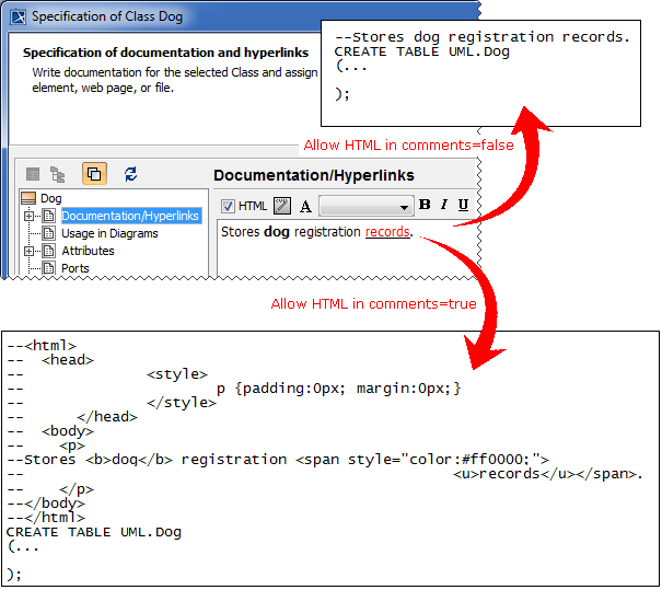 SQL comments with and without HTML formatting information.
Excluding elements from transformation
Elements can be excluded from the transformation in one of the following ways.
- By deselecting these elements in the 2nd step of the Model Transformation Wizard.
- By specifying rules for the automatic exclusion of elements in the 4th step of the wizard. These rules must be defined as executable opaque behaviors.
To define a rule for automatic elements’ exclusion
- Create an executable opaque behavior.
For more information, see Creating executable opaque behaviors in MagicDraw User Guide.
2. Create an input parameter, whose type is Element, the abstract UML metaclass, and multiplicity is [1].
3. Create a return parameter, whose type is java.lang.Object and multiplicity is [1].
4. Specify the Language and Body property value for the new opaque behavior.
Example
Let’s say we need to exclude from the transformation all the classes with the «pendingReview» stereotype applied.
For this, we must do the following.
- Select StructuredExpression as language of the opaque behavior body.
- Define the body by creating a TypeTest operation, which takes the collection of elements and returns only the ones with the «pendingReview» stereotype applied (see the following figure).
For more information about the TypeTest operation, see Calling operations from the model in MagicDraw User Guide.

Defining the body by creating a TypeTest operation in the Body and Language dialog box.
To specify the rules for the automatic elements’ exclusion from the transformation
- In the Transformation Details pane (the 4th step of the Model Transformation Wizard), click the Elements exclusion rules specification cell. The Edit button appears.
- Click the button and select one or more rules in the Select Opaque Behavior dialog.
- Click OK when you are done and continue the transformation setup process.
![]()