On this page
When simulating a model, you can choose to display simulation information not only in the Simulation window but in diagrams as well. For example, you can see runtime values directly on Part shapes or a flowing item with its name on a path.
Types of diagrams
You can display simulation information only in diagrams that are based on a Composite Structure Diagram. However, the flowing information on paths can also be shown in an Activity Diagram.
Displaying active States
In diagrams, active States can be displayed on the shapes of all initialized Parts a similar way they are displayed on the Variables pane of the Simulation window (in square brackets).
Exception
Active States are not displayed for Parts with the multiplicity of more than one.
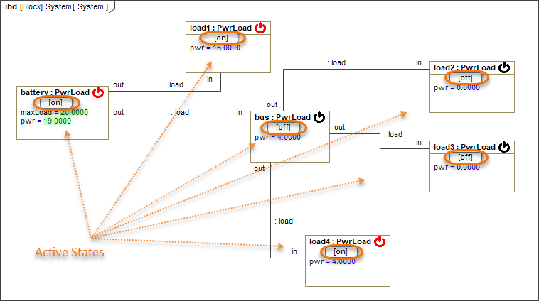
The diagram illustrates how active States are displayed on Part shapes.
If you do not want to see active States in diagrams during simulation, you can disable the Show Active States on Part Shapes animation option. For more information, see Disabling and enabling animation options.
Displaying active State images
You can display active State images on Part shapes by applying an image to a State or by assigning an Image Switcher to the Simulation Configuration from which you execute your model. When States change during simulation, State images change as well.
Important
If you specify State images both by applying them to States and assigning an Image Switcher to the Simulation Configuration, the images of the Image Switcher will be used when running the Simulation Configuration.
To display active State images when executing a model
- Open the Specification window of the State you want to create an image for.
- Click the specification cell of the Image property and select the image you want to use for a specific State. Click
 to select an image from the default image library, click
  to select an image from your file system, or click
  to specify an image URL.
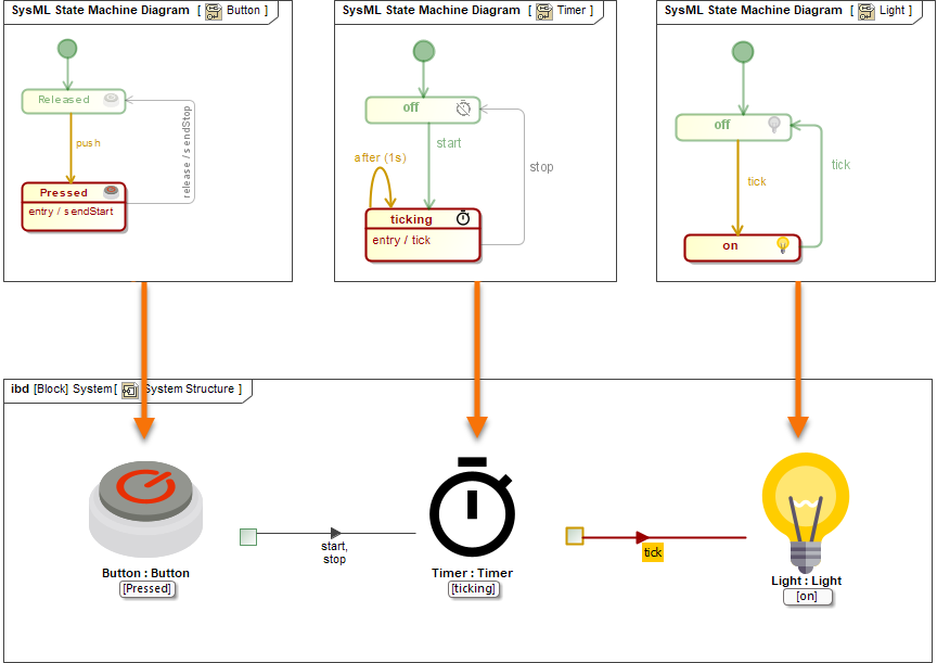
Here you can see how active State images are displayed when simulating a model.
If you run a Simulation Configuration, use an Image Switcher to display active State images as described below.
To display active State images when running a Simulation Configuration
- Open the Simulation Configuration Diagram in which the Simulation Configuration is displayed and create an Image Switcher.
- In the Specification window of the Image Switcher, click the Represents property specification cell and select the element for the states of which you want to create images.
For every active State image you want to create, create an Active Image element as the attribute of the Image Switcher.
Creating Active Image attributes
To create an Active Image attribute for an Image Switcher, click Active Image in the diagram palette, then click the Image Switcher shape.
In the Specification window of every Active Image specify the following properties:
Image property - select the image you want to use for a specific State. Click
to select an image from the default image library, click to select an image from your file system, or click to specify an image URL.Active Element property - select the State which the Active Image represents.
- Drag the Image Switcher created in step 1 to the Simulation Configuration shape. This way the Image Switcher is specified as the value of the UI property of the Simulation Configuration.
Displaying runtime values
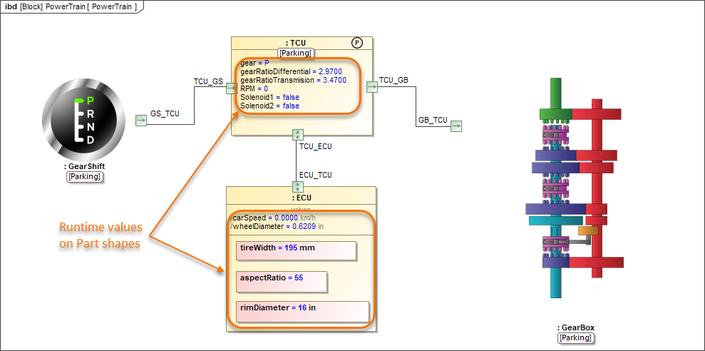
In diagrams, you can display the runtime values of Part properties the same way they are displayed in the Variables pane of the Simulation window. Runtime values are displayed next to property names on Part shapes instead of the default property values. Note that when you run a simulation, property types are not displayed.
Runtime values can be displayed only for the following types of properties:
- Primitive
- ValueType
- Enumeration
- Custom DataType
Automated Requirement verification
Runtime values on Part shapes are highlighted in green (the Requirement is satisfied) or red (the Requirement is not satisfied) when the automated Requirement verification is performed.
In addition, a tooltip with the text of unsatisfied Requirements or constraints appears when you hover the mouse pointer over Part or Value Property shapes.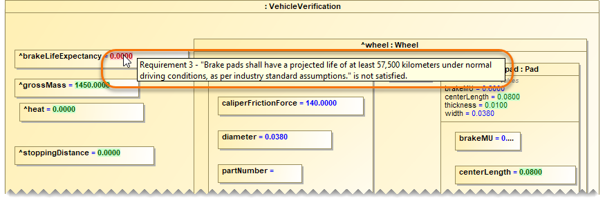
In this diagram, you can see how runtime values are displayed on Part shapes during model simulation.
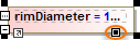
Resizing shapes to fit runtime values
If a runtime value does not fit in a shape and is cut off, resize the shape as described below.
- Select the shape that you want to resize.
- Do one of the following:
- Click the Resize to Fit Runtime Values icon on the shape (displayed below).
- Click
 in the diagram toolbar.
- Click the Resize to Fit Runtime Values icon on the shape (displayed below).
In addition, you can modify runtime values directly in diagrams and change simulation results in real-time. If you do not want to see runtime values in diagrams during simulation, you can disable the Show Runtime Values on Part Shapes animation option. For more information, see Disabling and enabling animation options.
Displaying flowing information
You can choose to display flowing information on animated paths when executing a model. In diagrams based on a Composite Structure Diagram, the flowing item is displayed as a moving triangle with a label showing the item name (see the image below). In Activity Diagrams, the flowing item is displayed as a bubble.
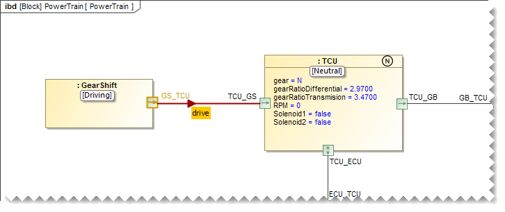
In this Internal Block Definition Diagram, you can see the neutral signal flowing from the GearShift to the TCU.
You can also send a trigger directly from a Part shape in a diagram and see the flowing item on a path. If you do not want to see flowing information in diagrams during simulation, you can disable the Show Flowing Information animation option. For more information, see Disabling and enabling animation options.
Disabling and enabling animation options
You can disable or enable animation options, such as displaying active States and runtime values on Part shapes. The steps below explain how to change option values for the whole project and a specific Simulation Configuration. Note that by default all simulation animation options are enabled.
To disable or enable animation options for a project
- In the main menu, go to Options > Project.
- On the left side of the Project Options dialog, expand the General option group and select Simulation.
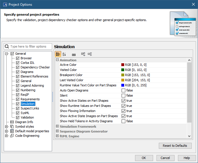
- In the option specification area on the right side of the dialog, disable or enable the following animation options:
- Show Active States on Part Shapes - if the option set to true, active States are displayed on Part shapes. Set the option to false to disable it.
- Show Runtime Values on Part Shapes - if the option set to true, runtime values are displayed on Part shapes. Set the option to false to disable it.
- Show Flowing Information - if the option set to true, the label of a flowing item is shown on paths. If the option is set to false, paths are only highlighted when an item is flowing.
- Show Active State Images on Part Shapes - if the option set to true, active State images are displayed on Part shapes.
- Click OK to save the changes.
To disable or enable animation options for a Simulation Configuration
- Open the Specification window of a Simulation Configuration element.
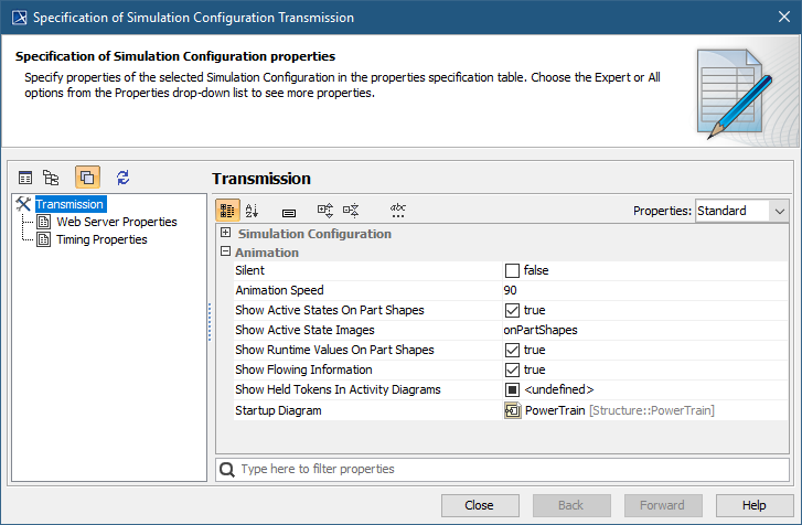
- Disable or enable the following animation options located in the Animation category:
- Show Active States on Part Shapes - if the option set to true, active States are displayed on Part Property shapes. Set the option to false to disable it.
Show Active State Images - Select On Part shapes to show active State images on Part shapes. Select In the Simulation UI to show active State images in the simulation UI dialog. To show images both on Part shapes and in the simulation UI dialog, select Both.
- Show Runtime Values on Part Shapes - if the option set to true, runtime values are displayed on Part shapes. Set the option to false to disable it.
- Show Flowing Information - if the option set to true, the label of a flowing item is shown on paths. If the option is set to false, paths are only highlighted when an item is flowing.
- Close the Specification window.