You can simulate an Interaction element, a (UML or SysML) Sequence diagram, or a Classifier whose Classifier Behavior is defined by an Interaction. This section demonstrates how to create a simple executable Interaction model through the following steps
- Create a Class containing two properties typed by different Classes.
- Create an opaque Behavior, owned by one of the two properties of the Class specified in (i), for printing the summation of two Integer input parameters.
- Write a script to print the summation of the two input parameters.
- Create an operation, owned by the properties specified in (i), and specify the opaque Behavior in (ii) as its method.
- Create an Interaction as the Classifier Behavior of the Class specified in (i).
- Create call message to call operation specified in (iv) by another property.
To create a Class containing two properties typed by different Classes
To create a new UML project, click File > New Project on the main menu. The New Project dialog will open.
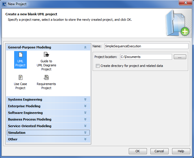
- Select UML Project from the General-Purpose Modeling group and specify the project's name, e.g., 'SimpleSequenceExecution'.
- Specify the location where you want to save your project file and click OK.
Right-click the Model node in the Containment tree and select Create Element > Class. A new Class element will be created. Name the created Class, e.g., 'System'.
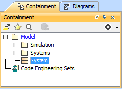
- Create two more Classes and name them, e.g., 'a' and 'b.
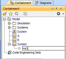
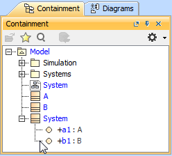
- Right-click the System model in the Containment tree and select Create Element > Property to create property for the Class. Name the property, e.g., 'a1'.
Right-click a1 and select the Specification window. Select A as the property type.
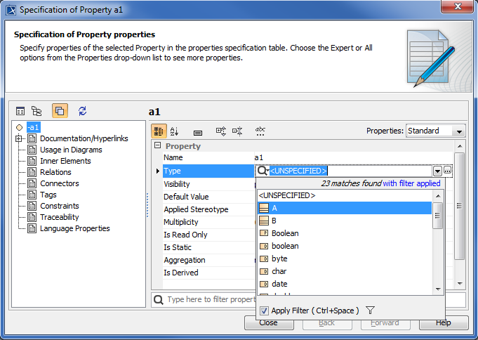
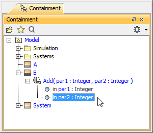
Repeat step 6 to create property b1 of type B (see the following figure).
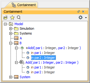
To create an opaque Behavior, owned by one of the two properties of the Class specified in ( a Class containing two properties typed by different Classes), to print the summation of two Integer input parameters
Right-click the Class B and select Create Element > Opaque Behavior. Name the opaque Behavior, e.g., 'Add'.
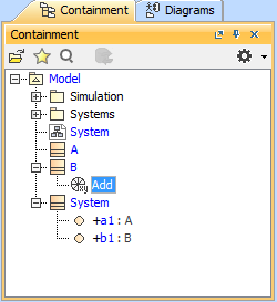
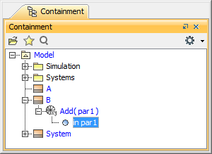
Right-click the opaque Behavior Add and select Create Element > Parameter to add a parameter element to the opaque Behavior. Name the parameter, e.g., 'par1'.
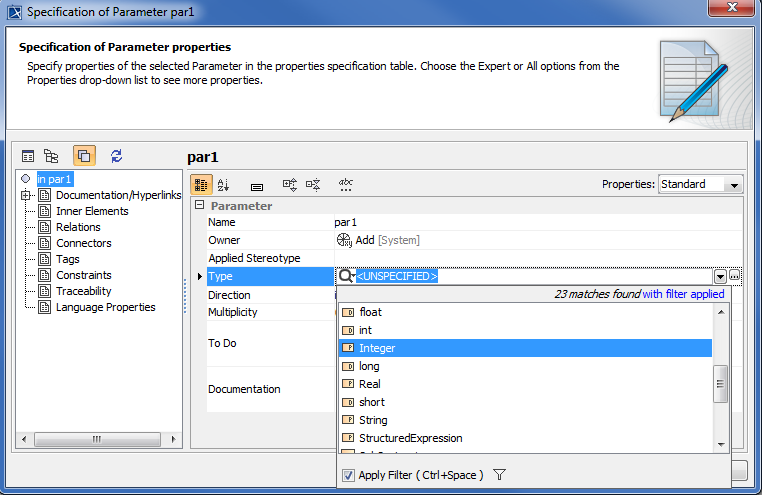
Right-click the parameter par1 and select the Specification window. Select Integer as the parameter type.
Repeat Step 2 to create another parameter and name it, e.g., 'par2' of type Integer.
To write a script to print the summation of the two input parameters
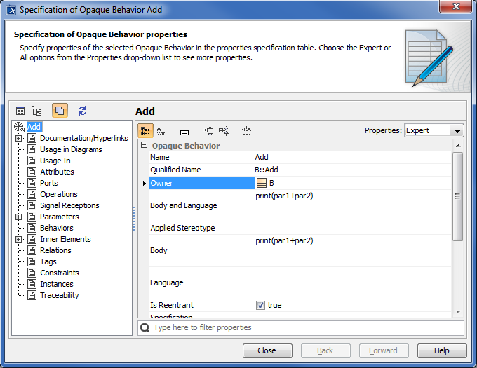
Open the Specification window of the opaque Behavior Add and write a script in the Body field (you can use any scripting language that is supported by MagicDraw Macro Engine, e.g., BeanShell, Groovy, JavaScript, Python, or Ruby). In this example, JavaScript is used: print(par1+par2); to print the summation of the two Integer parameters par1 and par2.
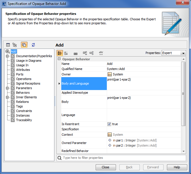
The Specification window of an Opaque Behavior.
To create an operation owned by the properties specified in (Class containing two properties typed by different Classes), and to specify the opaque Behavior as in (opaque Behavior owned by one of the two properties of the Class) as its method
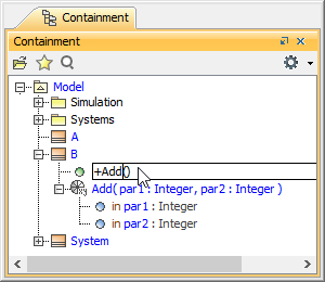
Right-click B and select Create Element > Operation to add an operation element to the Class. Name the operation, e.g., 'Add'.
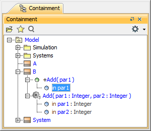
Right-click the operation Add and select Create Element > Parameter to add a parameter to the operation element. Name the parameter, e.g., 'par1'.
Right-click the parameter par1 and select Specification. Select Integer as the parameter type and in as the parameter direction. The Specification window of parameter par1 will be as follows
Repeat Step 2 and 3 to create another parameter. Name it, e.g., par2 of type Integer, having in as its direction. The parameters associated with the Operation will be as follows
- Right-click the operation Add and select Specification. The Specification window will open.
Select the opaque Behavior Add as the Method of the operation. The Specification window of the Opaque Behavior will be as follows
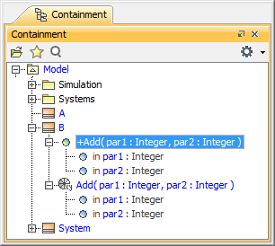
The parameters associated with an Operation in the Containment tree will be as follows.
To create an Interaction as the Classifier Behavior of the Class specified in (the Class containing two properties typed by different Classes)
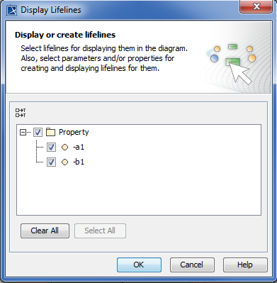
Right-click System and select New Diagram > Sequence Diagram. Select all properties in the Display Lifelines dialog and click OK.
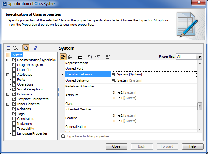
- Right-click the Class System in the containment browser and select Specification to open its Specification window.
Make sure that the Interaction System is the Classifier Behavior of the Class System.
To create a call message to call the operation specified in (operation owned by property) by another property
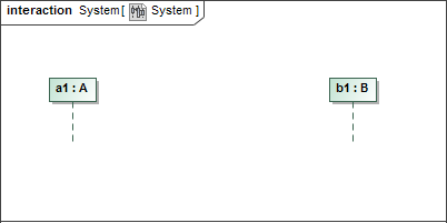
Double-click the Interaction System to open the Sequence diagram containing two lifelines: a1 and b1.
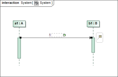
Select Call Message from the Diagram Modeling Elements toolbar and create a call message from a1 to b1.
 |
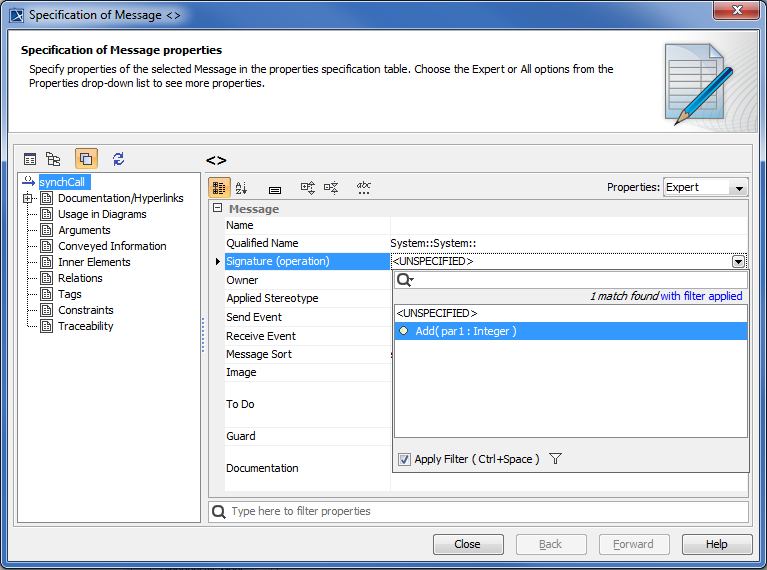
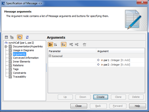
|Double-click the call message created in Step 2 to open the Specification window and select the operation Add as the Signature(operation) of the call message.
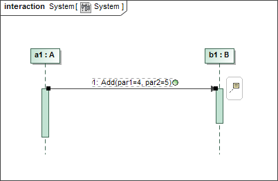
Select Argument on the left-hand side of the dialog to specify a value of the element. Type, e.g., 4 and 5 as the values of parameters par1 and par2 respectively. The Specification window of a call message showing its Arguments tags will be as follows
A Sequence diagram showing a call message between two lifelines will be as follows
Related pages