Behavioral diagrams (Activity diagrams, State Machine diagrams, and Sequence Diagrams) and Composite Structure diagrams (Internal Block diagrams) can be embedded into HTML-generated user interfaces and animated during the web server simulation.
Composite Structure diagrams only display activations and not run-time values.
Creating a UI Mockup with a State Machine Diagram
The sample model Joystick.mdzip is used to demonstrate how to create a UI Mockup with a State Machine Diagram.
To create a UI Mockup with a State Machine Diagram
- Open the <modeling_tool_install_dir>\samples\simulation\Joystick.mdzip sample file.
- Create a User Interface Modeling Diagram by adding a frame and panel to the diagram. To learn more about the components of a UI modeling diagram, refer to UI modeling diagram simulation.
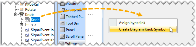
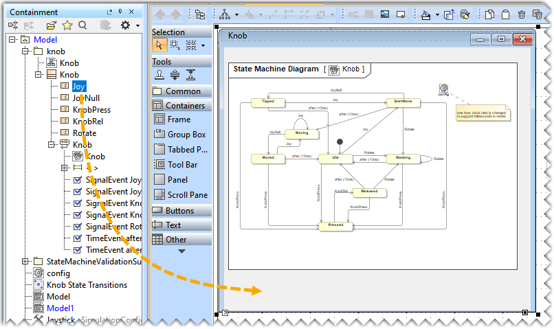
Drag the State Machine Diagram, long drop it on the frame, and select the Create Diagram Knob Symbol command.
- Click the diagram symbol in the frame to open the smart manipulator toolbar and click
 to view the diagram in the frame.
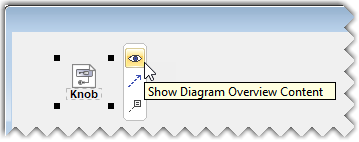
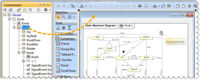
- Drag the Classifier from the Containment tree and drop it on the frame.
- Drag the Signals from the Containment tree and drop them on the frame to create Buttons.
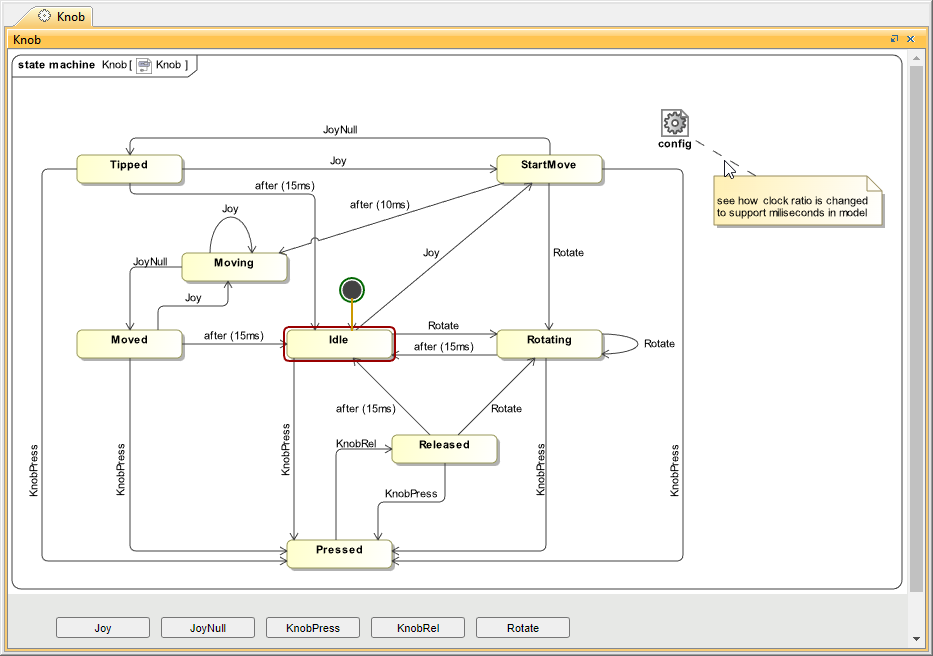
After completing the steps above, the diagram should look like the one below.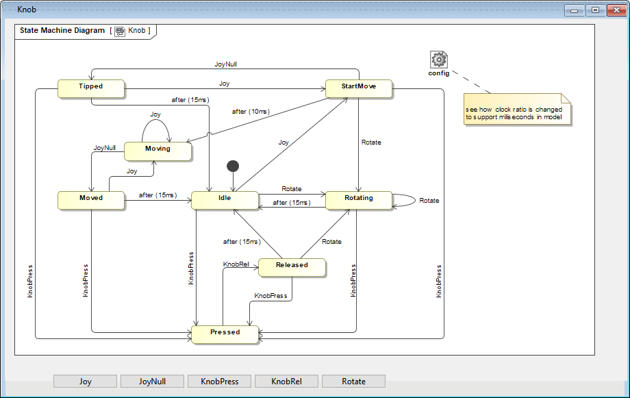
- Drag and drop the frame on the Simulation Configuration.
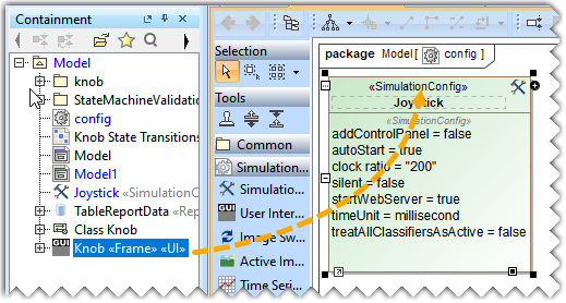
- Set the Start Web Server property to true in the Specification window of Sim Config.
- Click
 in the diagram toolbar to run the web server simulation for the generated UI Mockup.
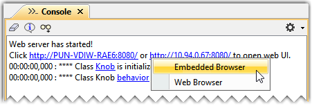
 - Click the URL that appears in the Console pane to open the Embedded Browser or the Web Browser.
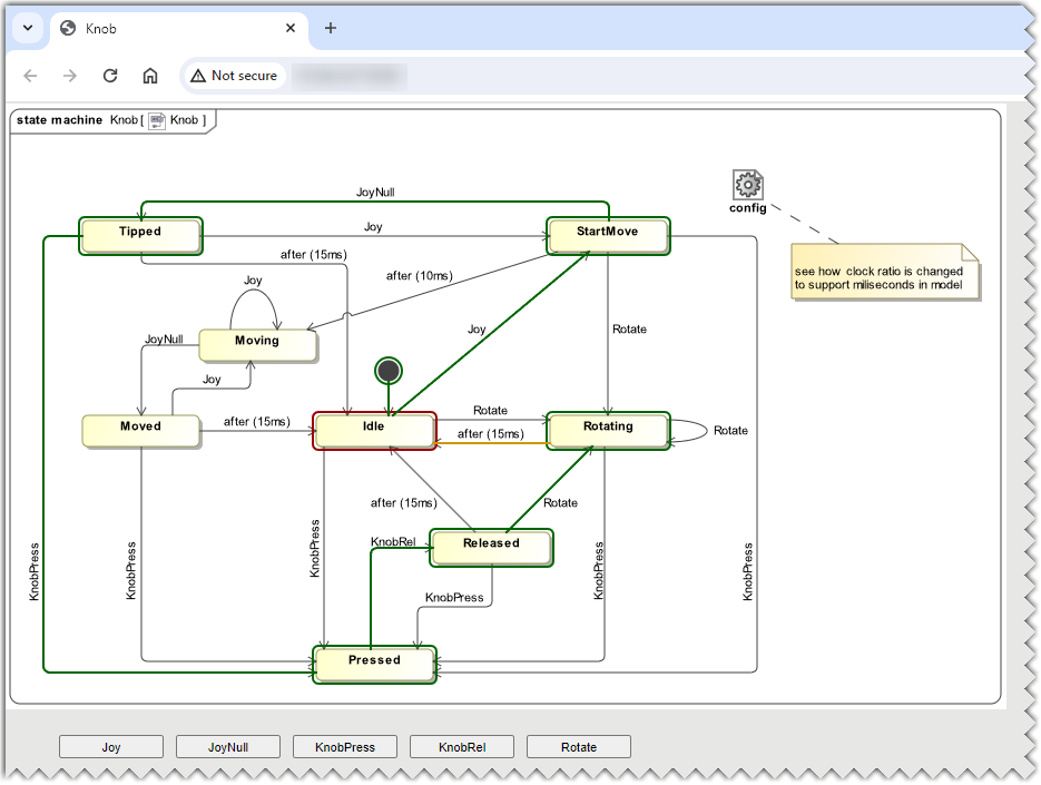
After creating a UI Mockup the Behavioral Diagram can be simulated both in the modeling tool and the web browser.
State Machine Diagram simulation on the Embedded browser.