On this page
Cameo Simulation Toolkit supports Simulink (MATLAB) co-simulation. Simulation executes the entire Simulink model (*.slx) on all steps, if there are any value changes in the input, which is similar to FMI. Simulation works with Simulink models as attached files and Simulink models located in the same directory of the project.
Warning
- You must successfully integrate MATLAB Version 2016b or later before using Simulink co-simulation. See Integration with MATLAB.
- Any duplicated Simulink model is not allowed in the project.
Note
- Simulink models without input/output Ports are not executed because there is no connectivity, and value change is not propagated to the Block.
- This type of Simulink integration is for atomic calculations. When any input changes, outputs such as the parametric diagram are calculated, e.g. In1 → Gain5 → Out1. It occurs as one step of Simulation time, the same as FMU.
- If the simulink file (.slx) is updated or modified, Simulation needs to restart the MATLAB session by calling the
kill matlabcommand in the Simulation console.
Using Simulink in an Internal Block/Parametric diagram
To import a Simulink model from the main menu, select File > Import From > Simulink File > Import > *.slx. You can also drag the Simulink file into the Block Definition diagram, Internal Block diagram, or Parametric diagram of the project. The Simulink Import Options dialog opens as shown below.
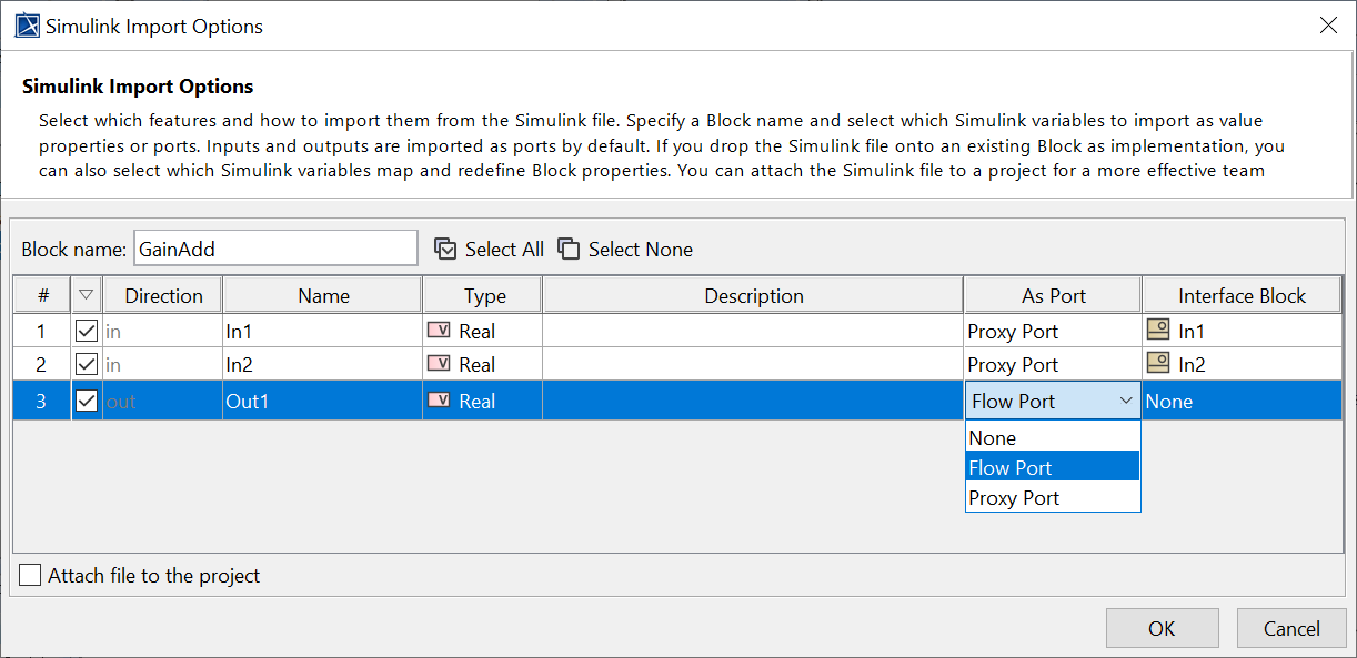
The Simulink Import Options dialog opens after importing a Simulink model into the project.
- All Input/Output Ports of the Simulink model are selected by default. However, you can select Proxy Port, Flow Port, or both of them in the same Block for the simulation, e.g., In1 and In2 Proxy Ports and Out1 Flow Port. The following scenarios apply:
- If you select the Proxy Port, you can select an existing Interface Block or <NEW> to automatically create a new Interface Block for each Port with «SimulinkBlock» applied as the model name with the Proxy Port. The automatically created Interface Block will have the default settings with In/Out In1/Out1 : Real «FlowProperty» according to I/O Ports of the Simulink model.
If you select the Flow Port, a Block with «SimulinkBlock» applied as the model name and the Flow Port with In/Out In1/Out1 : Real «FlowPort» according to I/O Ports of the Simulink model will be automatically created.
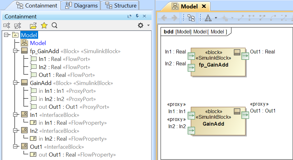
The Simulink model is created as Blocks with Proxy/Flow Ports.
Warning
- The Interface Block of a Proxy Port must have only a Flow Property.
- The names of the Proxy Port and Simulink I/O Port must be the same, e.g., In1-In1 and Out1-Out1.
Otherwise, an error message will be printed in the Simulation console, and the result will be invalid.
- Connect those Proxy/Flow ports through binding Connectors in the Internal Block/Parametric diagram.
- Run the simulation. When inputs are available for initialization (e.g., passed via binding), «SimulinkBlock» will be run at the first time and on every input change. You can also see animation of Flow Ports and set breakpoints for debugging.
From the figure below, a system is with two Simulink models: GainAdd and Gain5. GainAdd will multiply Port In1 by 10, multiply Port In2 by 2, and add the two results to Port Out1. Gain5 will multiply Port m by 5. Therefore, result will be [(2 * 10) + (2 * 2)] * 5 = 120.

The Simulink co-simulation result from the system which has two Simulink models (GainAdd.slx and Gain5.slx) connected via Flow Ports.
Using Simulink in an Activity diagram
A Simulink model can be used in the Activity diagram through drag-and-drop operation. The dropped Simulink file is presented as an Activity in the Containment tree with the same name as the Simulink model name, and «SimulinkBlock» is automatically applied. Parameters and directions are the same as the Simulink In/Out ports and can be used as a CallBehaviorAction on demand as shown in the figure below.
