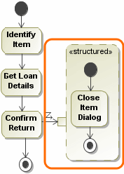
To understand the Use Case scenario representation in the Activity diagram, see the following table.

Use Case ScenarioMapping in Activity diagramExample
One (the first) Basic flow step
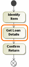
  1. The Activity with the Activity diagram is created under the owning Use Case just after the first basic flow step is created.
  2. The name of the created Activity and Activity diagram is the same as the owning Use Case name.
  3. In the Activity diagram, the Call Behavior Action is created for the basic flow step.
  4. The Initial Node is created before the Call Behavior Action.
  5. The Final Node is created after the Call Behavior Action.
  6. The Control Flow relationships are created from the Initial Node to the Call Behavior Action and from the Call Behavior Action to the Final Node.
One (the  first) Basic  flow step

Basic flow steps

  1. The Call Behavior Action is created for each basic flow step.
  2. The Initial Node is created before the first Call Behavior Action.
  3. The Final Node is created after the last Call Behavior Action.
  4. The Control Flow relationships are created from the Initial Node to the first Call Behavior Action, between each Call Behavior Action, and from the last Behavior Action to the Final Node.
Basic flow steps

Included use case

  1. The Call Behavior Action is created for the basic flow step of the included Use Case.
  2. The Call Behavior Action is inserted to the activity basic flow according to the order it was inserted in the basic flow.
  3. The Call Behavior Action is connected with the Control Flow relationships. The Call Behavior Action is not named.
  4. The Call Behavior Action has the Activity behavior defined. This Activity name corresponds to the name of the included Use Case.
  5. The activity (the Behavior or the Call Behavior Action) is owned by the included Use Case.
  6. If the included Use Case has its own Use Case scenario, this scenario is represented in the activity; the Activity diagram is created inside the Activity and flows are represented.

To represent the included Use Case from the Activity diagram to the Use Case scenario, you must follow all the rules. Additionally, you must connect the including Use Case with the included Use Case with the included relationship in your project.

Included use case
Extending use case (with the extension point)
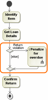
  1. The extending Use Case with the extension point is added as an alternative flow; the Decision and Merge nodes are created.
  2. The Decision node name corresponds the name of the alternative condition.
  3. The Call Behavior Action is created for the alternative flow step of the extending Use Case. The Call Behavior Action is not named.
  4. The Call Behavior Action has the Behavior defined: the Activity whose name corresponds to the name of the extending Use Case.
  5. The Activity (the Behavior or the Call Behavior Action) is owned by the extending Use Case.
  6. If the extending Use Case has its own Use Case scenario, this scenario is represented in the Activity diagram; the Activity diagram is created inside the Activity under the extending Use Case.
  7. The [else] Guard property is defined for the Control Flow created from the Decision node to the Merge node.

To represent the extending Use Case from the Activity diagram to the Use Case scenario, you must follow all the rules described above. Additionally, you must connect the extended Use Case with the extending Use Case with the extend relationship in your project.

Extending use case (with the extension point)
Extending use case (without any extension point)
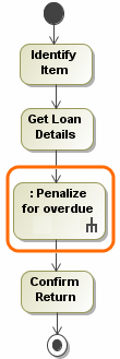
  1. The Call Behavior Action is created for the basic flow step of the Use Case scenario.
  2. The Call Behavior Action is connected with the Control Flow relationships according to the extending Use Case order in the basic flow.
  3. The Call Behavior Action is not named.
  4. The Call Behavior Action has the Behavior defined - the Activity whose name corresponds to the name of the extending Use Case.
  5. The Activity (the Behavior or the Call Behavior Action) is owned by the extending Use Case.
  6. If the extending Use Case has its own Use Case scenario, this scenario is represented in the Activity; the Activity diagram is created inside the Activity under the extending Use Case.

To represent the extending Use Case from the Activity diagram to the Use Case scenario, you must follow all the rules described above. Additionally, you must connect the extended Use Case with the extending Use Case with the extend relationship in your project.

Extending use case (without any extension point)

Alternative flow: alternative condition, alternative flow step

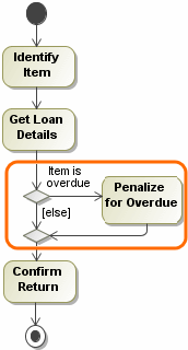
  1. The alternative flow is interrupted in the basic flow by using the Decision and Merge nodes.
  2. The Decision and Merge nodes are created after the Call Behavior Action. The Call Behavior Action in the Use Case scenario represents the basic flow step of this alternative flow. In other words, in an Activity diagram, the elements of the alternative flow are created after the basic flow step this alternative flow belongs to.
  3. The Decision node name corresponds to the name of the alternative condition.
  4. The Call Behavior Action is created for each alternative flow step.
  5. All these elements are connected with the Control Flow relationships.
  6. The [else] Guard property is defined for the Control Flow created from the Decision node to the Merge node.

Exceptional flow: exception type, exceptional flow step

  1. The Structured Activity Node with the Input Pin is created.
  2. The Call Behavior Action for which the exceptional flow was created is linked with the Input Pin using the Exception Handler relationship.
  3. The Class element is created under the Activity. The Class corresponds to the exception type in the Use Case scenario, that is, the Class name corresponds to the exception type name in the Use Case scenario.
  4. The Class is assigned to the Input Pin as a type property.
  5. In the Structured Activity Node the Call Behavior Action is created for each Exceptional Flow step.
  6. The Call Behavior Actions inside the Structured Activity Node are connected with the Control Flow relationships.
  7. In the Structured Activity Node the Initial Node is created before the first Call Behavior Action, and the Final Node is created after the last Call Behavior Action.
  8. In the Structured Activity Node, the Initial Node is connected with the first Call Behavior Action by using the Control Flow relationship and the last Call Behavior Action is connected with the Final Node by using the Control Flow relationship.