The Extract State Machine Wizard is used for extracting a selected part of a state machine diagram to a separate diagram. Using this wizard, you can:
- Create and specify the target diagram that will be created as the result of the extraction. The selected part will be extracted to the newly created diagram.
- Select the entry and exit points that will be created in a new diagram. The entry and exit points are listed for each intersected transition from the source diagram.
- Specify a referencing element that is created in the source state machine diagram and represents the elements moved to the target diagram during the extraction.
To start the Extract State Machine Wizard
- In the state machine diagram, select a part that you want to extract.
- From the selected part’s shortcut menu, choose Refactor > Extract. The Extract State Machine Wizard opens.
The Extract State Machine Wizard consists of three steps:
- Specification of a new element
- Creation of entry/exit points
- Specification of a submachine
Step #1. Specification of a new element
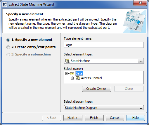
In this step, you can specify a diagram into which the extracted part will be moved. The new diagram will be created along with a new state machine. The diagram will be created as an inner state machine element. You can also define the element type, name, and the owner. Note, that the diagram name will be the same as the element name. The state machine type is selected by default.

| Element name | Description |
|---|---|
| Type element name | Type the name of the new element wherein the extracted part will be stored. The new element will contain the new diagram. |
| Select element type | Open the list and select the element type in which the extracted part and new diagram will be created. The default element type |
| Select owner | In the model tree, select a package, profile, or model as an owner of the newly created state machine. You can also:
|
| Select diagram type | Open the list and select the diagram type for the extracted part. The default diagram type is a state machine diagram. By using |
After you have specified the new element name, an owner of the element, and the type of the new diagram, do one of the following:
- Click Next , if you want to specify entry/exit points and define a referencing element. The next wizard step opens.
- Click Finish. The selected part of a state machine diagram is extracted to a new diagram that is specified in this step. Instead of the extracted part, the submachine state is created referencing to the newly created diagram. The second and the third wizard steps are skipped - that is the default options are taken.
Step #2. Creation of entry/exit points
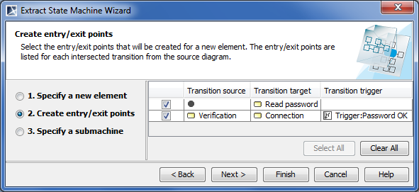
The entry and exit points that will be created for the intersected transitions are listed in this step.

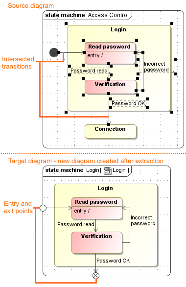
As you can see in the example, in the Access Control source diagram, the intersected transitions are selected for the extraction. After the extraction, in the target diagram, the entry and exit points are created for each intersected transition.
In the Extract State Machine Wizard, the Create entry/exit point step is empty unless there are intersected transitions selected in the source state machine diagram.

After you have selected the parameters, do one of the following:
- Click Back to return to the first step.
- Click Next to define a referencing element. The next wizard step opens.
- Click Finish. The selected part of the state machine diagram is extracted to a new diagram. The third wizard step is skipped - that is the default submachine name is taken.
Step #3. Specification of a submachine
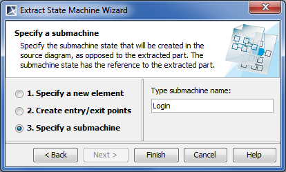
A referencing element is created in the source diagram instead of the extracted part. Double-click the referencing element to navigate to the extracted part.

After you have typed the submachine name, do one of the following:
- Click Back to return to the second step.
- Click Finish. The selected part of the state machine diagram is extracted to the new state machine diagram.