If you want to reuse the style and layout of Class with its Ports in another diagram, you need to define the appearance of the Class, the style, and position of its Ports in the Class diagram. It means that you define a new layout template. When defining the appearance of the Class, you can change its color, font, size, layout, and other style properties. To do this, follow the procedure below.
Important
Only one Class shape with its Ports can be defined in one layout template diagram.
To define the layout template
- Create the Class diagram. How to create diagrams >
- Create a new or represent an existing Class with its Ports on the diagram pane.
- Specify the appearance of all shapes by using the Symbol Properties dialog and diagram toolbar.
Set the positions of Ports on Class shape manually.
The appearance of Class and its Ports shapes are defined (see the figure below).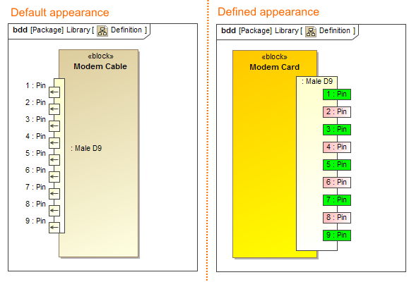 The comparison of default and defined appearance of the Modem Card Block, style, and the position of its ports. The illustration displays concepts from SysML Plugin.
Composite Structure Diagram as a layout template
- From the version 19.0 SP1, you can define the appearance and layout of a Part Property with its Ports in the Composite Structure Diagram and set this diagram as layout template.
- If a Composite Structure Diagram displays several Part Properties, create a layout template directly from a particular Part Property. It's appearance and layout will be copied to the template automatically.
The sample models used in the figure of this page are Modem Cable that comes with SysML Plugin. To open those samples properly you need to install the SysML plugin in the MagicDraw and download Modem Cable Layout Templates.mdzip.