The Customize Diagram Wizard contains the following steps for creating a new diagram type or modifying a chosen one.
All Custom Diagrams are based on standard UML diagrams (like Class, Use Case, Sequence, and other).
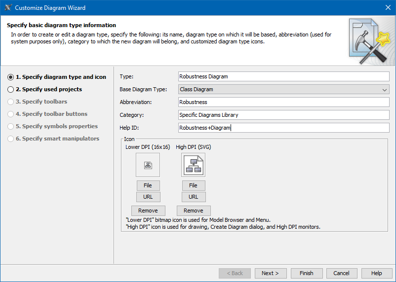
Step 1: Specify diagram type and icon
To create your own diagram, first specify the following properties
- Diagram type name (for example, Robustness Diagram).
- Base Diagram Type – standard UML diagram to be extended. All configurations, semantics, and other settings will be inherited from this diagram type.
- Abbreviation – a short form of the diagram name. It will be used in Diagram Frames header or Diagram shapes in Content diagrams.
- Category – creates your specific category in the Diagrams menu or in the Create Diagram command list. You can store all your customized diagrams in this category. If you leave this field empty, the customized diagrams will be added to the Custom Diagrams category.
- Help ID – sets a specific Help ID to invoke help or documentation topics.
Icons – several icons for your custom diagram representation in MagicDraw GUI.
A custom diagram icon that you can upload from your file system must be in .gif, .jpg, .jpeg, .svg, .png., or .wmf file format.
Step 2: Specify used projects
Custom Diagrams are oriented to a new specific domain, technology or platform, and are often based on a custom profile.
Select the required used projects or local profiles. How to use a custom server profile see in customizing diagram palette.
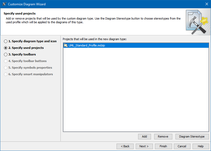
- Selected profiles must be local, the server profiles cannot be used.
- Do not remove the UML Standard Profile, which is selected by default, from the list. It must be used by any custom diagram type.
The custom diagram could use stereotyped elements. Profiles defining these stereotypes must be used by the custom diagram. The selected used projects or profiles load when a user creates a custom diagram in a project. You can choose a stereotype for the diagram by clicking the Diagram Stereotype button.
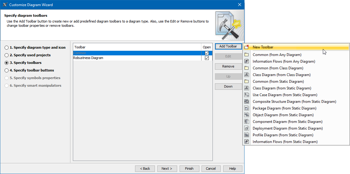
Step 3: Specify Toolbars
Every diagram differs by the elements used in them. In the Specify toolbars step, you can group standard or custom elements.
Only toolbars compatible with the specific diagram type can be added.
You can:
- Create your own custom diagram toolbar.
- Create your own toolbar, name it, and select an icon.
- Choose standard toolbars that will be visible in your diagram.
- Select existing toolbars inherited from the base diagram type.
- Arrange the order of toolbars by using "Up" and "Down" buttons.
- Select which toolbars will expand or collapse by default (use the Open check box).
Step 4: Specify Toolbar Buttons
Select standard or stereotyped elements for your custom diagram toolbars.
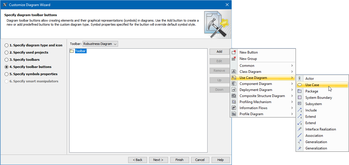
Click Add and select standard UML elements or click Add and then New Button to create your own buttons to create customized or stereotyped elements.
Only buttons compatible with the specific diagram type can be added to the toolbar.
Customize the following properties when creating a new button:
- Model element type
- Custom icon for a button
- Shortcut that activates the button
- Tooltip description
- Stereotype(s) to apply to the created element
- Symbol style – selected symbol properties will be used only when the element is created using this button
- Default values for some primitive model element properties (like isAbstract = true or similar)
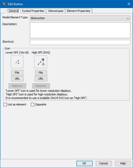
- List as element – select this check box to add the button as a command in the Create Element command list.
- Opposite – this check box is only available for relationship buttons. Select it to add the opposite relationship button.
Step 5: Specify Symbol Properties
This step allows you to customize the style for any element appearing in your custom diagram (e.g. a class dropped in your diagram should be suppressed and red).
You can change the appearance of standard symbols, symbols of stereotyped elements, and the custom diagram itself. The customized element style will be used only in the appropriate custom diagram type.
Step 6: Specify Smart Manipulators
Only elements and relationships that are available in the toolbars specified for the diagram being customized can be added to the smart manipulator of the element shape or path.
Smart manipulators are special buttons that appear in the pop-up window when a shape or path is selected on a diagram.
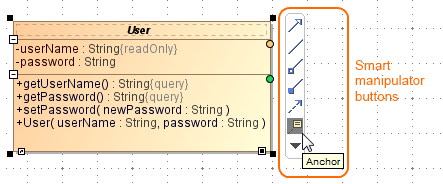
Example of smart manipulator
You can configure the element or kind of relationship suggested when a custom shape or path is selected on a diagram.
There are three main sub-steps:
- Create a new configuration (or modify an existing one). Select the element to customize. The smart manipulators configuration can be related to:
- Element, displayed as [Element name]
- Element + stereotype(s)
- Symbol, displayed as {Symbol name}
- Symbol + stereotype(s)
- Stereotype(s), displayed as «Stereotype name»
- Select suggested relationships for the selected configuration.
- Select target elements for the selected relationship.
If several configuration settings could be applied to the same selected element on the diagram, only one configuration will be used according to this priority:
# | Configuration | Comment |
1 | Symbol + stereotype(s) | When stereotype(s) for symbol applied |
2 | Stereotype |
|
3 | Symbol |
|
4 | Element + stereotype(s) | When stereotype(s) for element applied |
5 | Element |
|
If several configurations are created for a few stereotypes (for example, Stereotype1 and Stereotype2) in the same diagram, when both stereotypes are applied to one symbol on that diagram pane, the first configuration (in this case, Stereotype1) is used, unless you specify a symbol+ stereotype(s) configuration.
Inheritance of configurations
All diagrams inherit their configurations from a base diagram (example: in this hierarchy: Any diagram > Static diagram > Class diagram > Generic DDL diagram).
If you add a new configuration to a class diagram (for example, Symbol A + stereotype B), the configuration will be used in the generic DDL diagram, as the class diagram is its base diagram. Any static diagrams will not have such configurations.
To change the configuration from the base diagram type
- From the Configurations list, select the configuration by the element type and choose the Specify own configuration button. This overwrites the inherited configuration.