The following steps show you how to work with messages:
Assigning a message to a connector
To assign a message to a connector
- On the diagram palette, click the button corresponding to the desired Message type.
Click a desired connector on the diagram pane. A Message arrow will be placed on the selected connector.
A Message flow has two directions: right and left. Choose one of them by clicking the associated button on the diagram palette.

Setting/removing the advanced numbering of messages
To set/remove the advanced numbering of messages
- From the diagram shortcut menu, select Numbering.
- Select to set, or clear to remove the Use Advanced Numbering.
Changing current message numbering
To change current message numbering
- From the diagram shortcut menu, select Numbering > Change Numbering.
- Increase, decrease, and / or change the level of numbering in the Change Communication Numbering dialog.
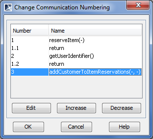
If the Edit button is inactive, remove the automatic advanced numbering of Messages.
Displaying messages
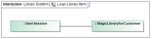
If you want to display messages on connectors in the Communication diagram you must first implement the following conditions (see the figure below):
- Messages are assigned to connectors. How to assign a message to connector >
- The lifeline shapes are already displayed on the diagram pane. How to display lifelines >
- The paths between lifelines are displayed on the diagram pane. How to display paths >
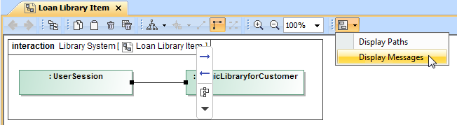
To display messages
- Select the connector between lifelines.
- Perform one of the following actions:
- Right-click the connector to open the shortcut menu, and select Display > Display Messages.
- On the diagram toolbar, click
 ,and select Display Messages.
- In the opened Select Messages dialog, select the messages you want to display, and click OK.
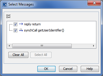
Messages of the selected connector are displayed on the diagram pane.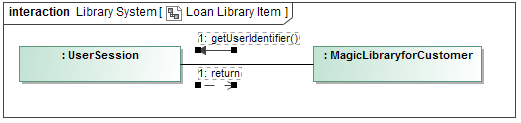
Sample model
The model used in the figures of this page is the Communication diagram sample model. To open this sample do one of the following:
- Download communication diagram.mdzip.
- Find in modeling tool <modeling tool installation directory>\samples\diagrams\communication diagram.mdzip.