After you have created a Use Case scenario, you can represent this scenario in an Activity diagram. The following procedure describes how to represent the Use Case scenario in the Activity diagram and how to turn the automatic layout on or off in the Activity diagram when representing the Use Case scenario.
To represent a Use Case scenario in an Activity diagram
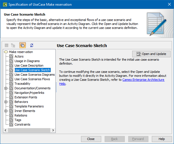
- Open the Use Case Specification window and click the Use Case Scenario Sketch property group.
- Click the Open Activity Diagram button
 . The Activity diagram opens with the Use Case scenario represented on it.
You need to reopen the Activity diagram each time after you make modifications to the Use Case scenario in the Specification window. Modifications to the Activity diagram where the Use Case scenario is represented automatically appear in the textual Use Case scenario.
For Use Cases having read-only accessibility, the use Case Scenario cannot be represented on the Activity diagram.
In the Activity diagram, all symbols are laid out automatically every time the diagram is opened.
To leave symbols in the same place while opening the Activity diagram after modifying the Use Case scenario in the Specification window, change the Layout use case scenario activity diagram option value to false. This option appears in the Project Options dialog, in the General project options group.
Your modeling tool might not be able to interpret the Use Case scenario in some cases. These are the most common reasons why:
| There is no merge node or call behavior action after the element. |
| There is no initial node in Activity. |
| There is no final node in Activity. |
| There are no outgoing control flows from the element. |
| There is no merge node after the element. |
| There are no outgoing flows from the element. |
| There is no alternative flow step after the element. |
| Cyclic scenario. |