On this page
Introduction
You can display ports, properties, and deep nested properties that have already been created in all structure diagrams. This functionality is driven by stereotypes, which allow you to display properties on which stereotypes have been applied. If you have applied your own stereotypes for the elements (e.g., electrical, mechanical, optical), you can use those stereotypes when selecting the properties you want to display on the diagram pane.
Note
For more information about how to create custom stereotypes and apply them, see UML Profiling and DSL Guide.
This page contains the following information:
Ways to display parts and ports
You can display ports and properties in the following ways:
Using the Display Parts/Ports dialog
You can use the Display Parts/Ports dialog to control how much of a structure should be displayed. The Display Parts/Ports dialog opens automatically when creating a new Composite Structure diagram for a Class element that owns properties. It can also be accessed and opened in the structure diagrams that have already been created. The Display Parts/Ports dialog allows you to:
- Preview all Parts, Ports, and other properties in one place.
- Manually or automatically select required Parts, Ports, and other properties you want to display.
- Manually or automatically choose deeply nested Parts, Ports, and other properties you want to display.
- Define layout options for Parts.
- Specify layout options for Ports.
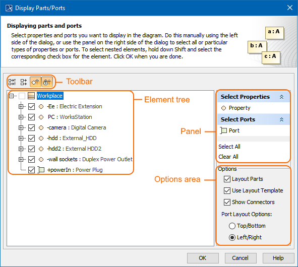
The Display Parts/Ports dialog consists of the following areas:
- Dialog toolbar allows you to show or hide additional information about listed elements.
- Element tree displays all owned internal structure of context Class.
- Panel is a context-sensitive area that depends on the selected property from the Element tree. It allows you to batch select Parts/Ports in the Element tree. You can select all, clear all, or choose only properties by type, stereotype, or aspect.
- Options area allows you to choose the layout of the selected parts and Ports when they appear in the diagram.
The following procedure will guide in working with the Display Parts/Ports dialog when you want to display required properties on the diagram pane.
To display Ports and Properties using the Display Parts/Ports dialog
Open the Display Parts/Ports dialog:
- When creating a new Composite Structure diagram, the dialog opens automatically.
- When editing an already created structure diagram , the dialog can be opened in the following ways:
- Select either a diagram frame or single/multiple element shapes, and, on the diagram toolbar, click and choose Display Parts/Ports.
- Right-click either a diagram frame or single/multiple element shapes, and select Display > Display Parts/Ports.
- (Optional) Enable buttons from the Display Parts/Ports dialog toolbar if you want to show or hide additional information about listed elements:
- Click
 to show the full path of elements.
 - Click
 to show the full types of elements.
 - Click
 to show the inherited elements.
 - Click
 to show the inherited properties.
- Click
Choose the properties you want to display by using one or more of the following methods:
Warning
If some check boxes are inactive in the element list, those elements are already displayed in the diagram.
Use the element tree located on the left side of the dialog:
- Manually select individual check boxes one by one.
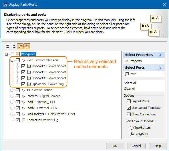
- Select recursively nested elements by holding down the Shift key while selecting the corresponding check box for the element.Example 1
All properties (socket1, socket2, socket3, powerIn) of the Ee Property are selected recursively by holding down the Shift key while selecting the corresponding check box from the element tree in the Display Parts/Ports dialog.
Use the context-sensitive panel located on the right side of the dialog:
- Select Properties group - displays all property types (including your own stereotypes) that are owned by the selected element from the element tree located on the left side of the dialog.
- Select Ports group - displays all Port types (including your own stereotypes) that are owned by a selected element from the element tree located on the left side of the dialog.
- Select All - selects all check boxes that are expanded from the element tree located on the left side of the dialog.
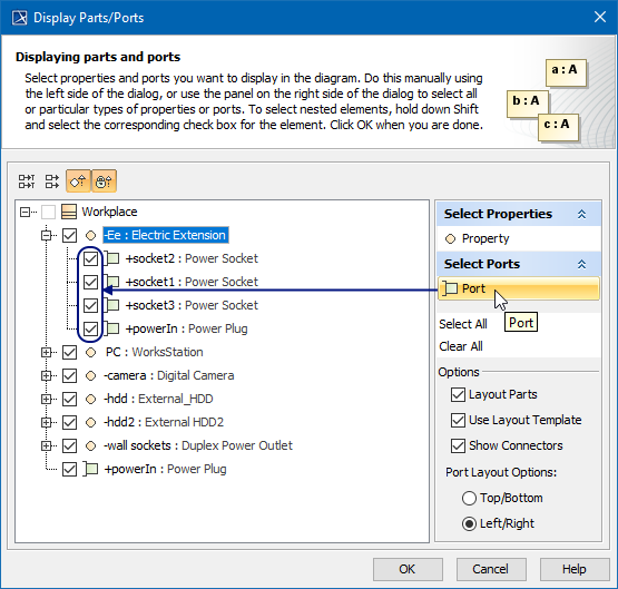
- Clear All - clears all check boxes, even those that are collapsed (deep nested), from the element tree located on the left side of the dialog.Example 2
All ports (socket1, socket2, socket3, powerIn) of the Ee Property are selected in the element tree by using the Select Ports group in the context-sensitive panel of the Display Parts/Ports dialog.
- Specify the layout options in the Options area:
- Parts layout: select the Layout Parts check box if you want the Part shapes to be arranged in the automatic layout.
- Usage of layout template: select the Use Layout Template check box if you want the layout template to be applied. When this check box is selected, the Part, which is included in the layout template, and all its Ports from the layout template are selected automatically.
- Showing connectors: select the Show Connectors check box if you want the connectors to be displayed.
- Ports layout on Parts shape:
- Top/Bottom - displays Ports on the Part shape from top to bottom.
- Left/Right - displays Ports on the Part shape from left to right.
- Click OK.
After those steps, all parts, ports, other properties that were selected in the Display Parts/Ports dialog are displayed on the diagram pane.
Using the diagram toolbar and the shortcut menu
In the structure diagrams that have already been created, you can display Ports, Properties, and hide all Ports by using the commands from:
- The Display button on the diagram toolbar.
- The Display command group under the shortcut menu.
You can also use the Display button and Display command group from the shortcut menu as their functions are identical. All those commands are interactive and depend upon the selection on the diagram pane. For example, if the Part shape is selected on the diagram pane, the both menu contains only the commands that can be applied to the selected Part shape. If you select nothing in the diagram pane, both the menu shows commands that can be applied to the whole diagram.
These commands under the Display button and shortcut menu are comprised of elements that are still not displayed on the diagram according to their:
- Metatypes.
- Stereotypes.
- Types stereotypes.
The following procedures will show you how to:
- How to display Ports, Properties using the Display button.
- How to display Ports, Properties using the shortcut menu.
- How to hide Ports.
To display Ports, Properties using the Display button
- Select either a diagram frame or single/multiple element shapes.
- On the diagram toolbar, click .
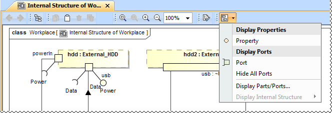
From the opened command menu, select the required properties to display:
- All Ports that are available to display are listed under the Display Ports command group.Important
If nothing is selected on the diagram pane, the Display Ports command group will contain commands that allow you to display two levels of structure: ports are displayed on the diagram frame and on the first level parts.
- All Properties that are available to display are listed under the Display Properties command group.
After selecting the required command from the Display button, the appropriate properties are displayed on the diagram pane.
To display Ports, Properties using the shortcut menu
- Right-click either the diagram pane or single/multiple element shapes.
- From the shortcut menu, select the Display command group.
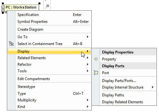
From the opened command menu, select the required properties to display:
- All Ports that are available to display are listed under the Display Ports command group.Important
If nothing is selected on the diagram pane, the Display Ports command group allows you to display two levels of structure: ports are displayed on the diagram frame and on the first level parts.
- All Properties that are available to display are listed under the Display Properties command group.
After selecting the required command from the Display command menu, the appropriate properties, Ports are displayed onto the diagram pane.
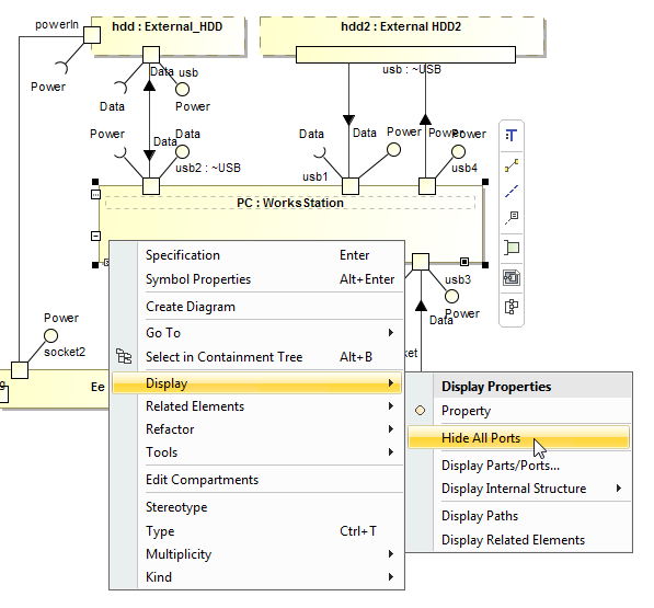
To hide Ports
- Select either a diagram pane or any number of element shapes, and, on the diagram toolbar, click and choose Hide All Ports.
Right-click either a diagram pane or any number of element shapes, and select Display > Hide All Ports.
After selecting the command, the Ports of the selected shape will be hidden from the diagram pane, but not removed from the model.Warning
If the Hide All Ports command doesn't appear, the selection or diagram doesn't contain any Ports that can be hidden.
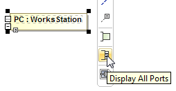
Using the smart manipulator toolbar
When the properties are already displayed on the structure diagrams, you can display their direct ports using the Display All Ports button from the smart manipulator toolbar. It does not allow you to display deeply nested ports, only first level ports. To display deeply nested ports, you should use the Display Parts/Ports dialog. Follow the steps below to learn how to display ports of a selected property shape.
To display Ports on shapes
- Select the required element shape or a diagram frame.
From the smart manipulator toolbar, click
 .
.
All first level Ports of the selected shape will be displayed on the diagram pane.Warning
If the Display All Ports button is not available, the selected element or diagram doesn't own any Port.
Using the drag-and-drop operation in the Composite Structure diagram
The most efficient way to create a new property and display it with all Ports in the Composite Structure diagram is by dragging the Class or Property elements. This method does not allow you to display deeply nested properties, only first level properties. To display deeply nested elements, use the Display Parts/Ports dialog. The following procedures will show you:
- How to create a Property shape and how to display all its Ports when dragging the Class element.
- How to display a Property shape and all its Ports by dragging the Property element.
You can create a new Property by dragging the Class element from the Model Browser to the Composite Structure diagram pane. The newly created Property will be typed by the dragged Class and displayed on the diagram pane. If this Class has Ports defined, you can display them by using the long drag, and selecting an appropriate option from the opened menu (see Example 3).
To create and display a Property by dragging a Class element
Drag a single or a multiple Class element from the Model Browser onto the diagram pane.
Drag a single or a multiple Class element from the Model Browser onto the diagram pane, and hold it down until the Tooltip appears (long drag). Drop it, and, from the opened menu, select the Create Property Symbol command.
The new Property is created in the model and displayed on the diagram pane. The newly created Property is typed by the dragged Class automatically.
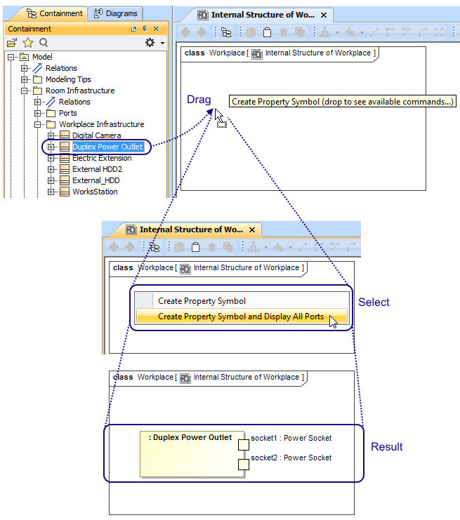
To create and display a Property and display all its Ports by dragging a Class element
- Drag a single or a multiple Class element from the Model Browser onto the diagram pane, and hold it down until the Tooltip appears (long drag).
- Drop it, and, from the opened menu, select the Create Property Symbol and Display All Ports command.
The new Property is created in the model and displayed with all its Ports on the diagram pane. The newly created Property is typed by the dragged Class automatically.
Tip
After creating an element, it is beneficial to find its location in the model tree by performing one of the following:
- Right-click the shape, and, from the shortcut menu, choose the Select in Containment Tree command.
- Select the shape and press Alt+B.
Example 3
After selecting the Create Property Symbol and Display All Ports command, and dragging (long drag) the Class element to Internal Structure of Workplace diagram pane, it creates a new Property typed by a Duplex Power Outlet Class and displays all Ports on it.
You can display a Property shape by dragging a Property element from the Model Browser to the Composite Structure diagram pane. If this property has Ports defined, you can display them by using the long drag, and selecting an appropriate option from the opened menu (see Example 4).
The following procedures describe how to display Property shape and all its Ports by dragging the Property element.
To display a Property by dragging a Property element
- Drag a single or a multiple Property element from the Model Browser onto the diagram pane.
- Drag a single or a multiple Property element from the Model Browser onto the diagram pane, and hold it down until the Tooltip appears (long drag). Drop it, and, from the opened menu, select the Create Property Symbol command.
The Property shape is displayed on the diagram pane.
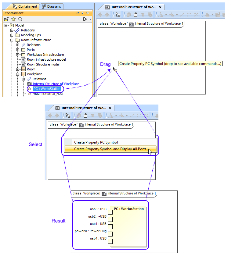
To display a Property with all of its Ports by dragging a Property element
- Drag a single or a multiple Property element from the Model Browser onto the diagram pane, and hold it down until the Tooltip appears (long drag).
- Drop it, and, from the opened menu, select the Create Property Symbol and Display All Ports command.
The Property shape is displayed with all its Ports on that shape.
After selecting the Create Property Symbol and Display All Ports command, and dragging (long drag) the Property element to Internal Structure of Workplace diagram, it displays Property shape and all Ports on it.
After completing the steps outlined above, the Property shape and/or all its Ports are displayed on the Composite Structure diagram.
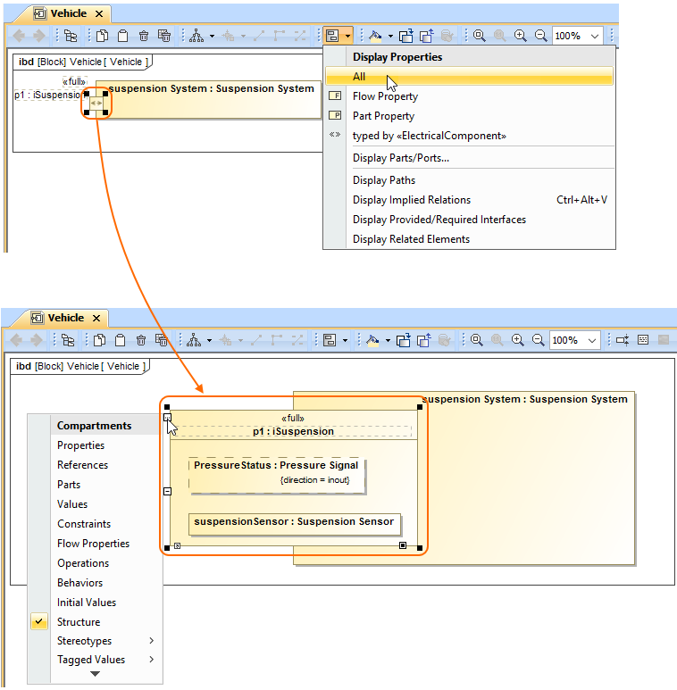
Displaying properties of a Port
If you display properties of a Port, all properties of its type will be displayed inside the Port shape and part compartments will be enabled for that Port.
To enable Part compartments on the Port shape
- Select a Port shape whose type has properties.
- Do one of the following:
- On the diagram toolbar, click .
- From the shortcut menu, point to the Display command group.
- On the diagram toolbar, click
- Select the required properties to display.
The properties are displayed inside the Port shape. Part compartments are enabled for the Port.
The example below shows the p1 Port both before and after displaying its type properties. The properties displayed on the Port shape are the Pressure Status Flow Property and the suspensionSensor Part Property, which are the properties of the selected Port type iSuspension Block. After display of properties has been selected, compartments are automatically enabled for the p1 Port.
Sample model
The models used in the figures of this page are:
- The Composite structure diagram sample model that comes with MagicDraw. To open this sample do one of the following: download composite structure diagram.mdzip or find in modeling tool <modeling tool installation directory>\samples\diagrams\composite structure diagram.mdzip.
- The Vehicle parts under ports sample model which is available only with SysML Plugin. To open this sample download Vehicle parts under ports.mdzip.