Magic Model Analyst
Released on: February 12, 2021
In this release, Magic Model Analyst brings quite a few powerful features that will change the way you simulate your models. Now you can use diagrams as a simulation dashboard: provide value inputs or read outputs with the help of widgets, view and change runtime values directly on Part shapes, display active states and active state images in diagrams, etc. In addition, streaming behavior simulation is now supported, simulation options have been moved to Project Options for your convenience, animation delay affects only visible diagrams to provide better user experience, guard evaluation on transitions expressed in natural language are now interactive, and more.
HTML Widgets in IBD Diagrams
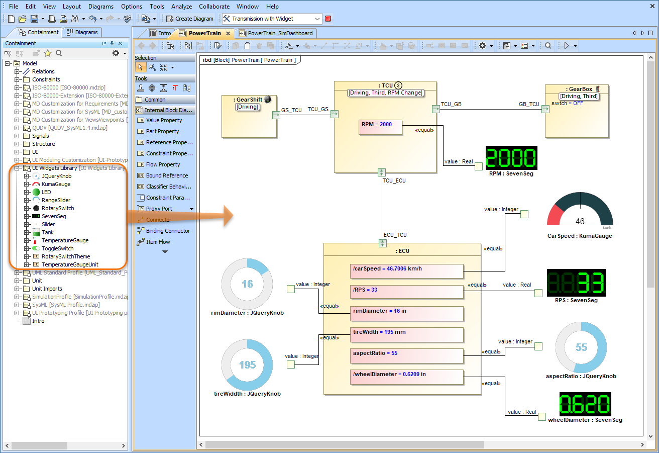
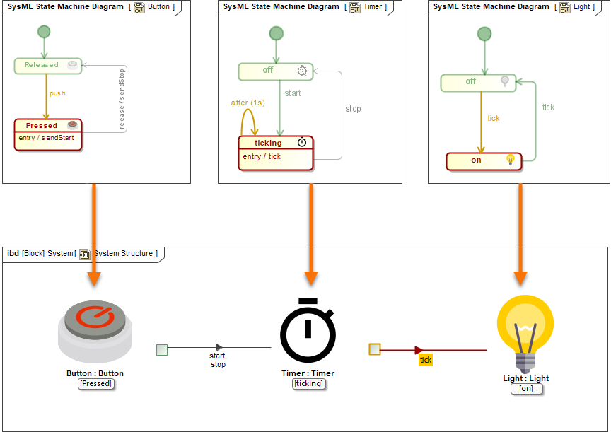
Magic Model Analyst introduces a new powerful mechanism to integrate any third-party interactive HTML components (widgets) into SysML diagrams for simulation. A set of predefined widgets is available in UI Widgets Library. You can drag and drop widgets to IBD diagrams and connect them to appropriate value properties to provide inputs or read outputs. If you have basic HTML and JavaScript skills, you can manually create new custom widgets and integrate them into simulation.
Please note that the free Web Server for Cameo Simulation Tookit plugin is required for this functionality.
The example of using widgets from UI Widgets Library in an Internal Block Definition Diagram.
Learn more about integrating widgets for simulation >>
Streaming Activity Simulation
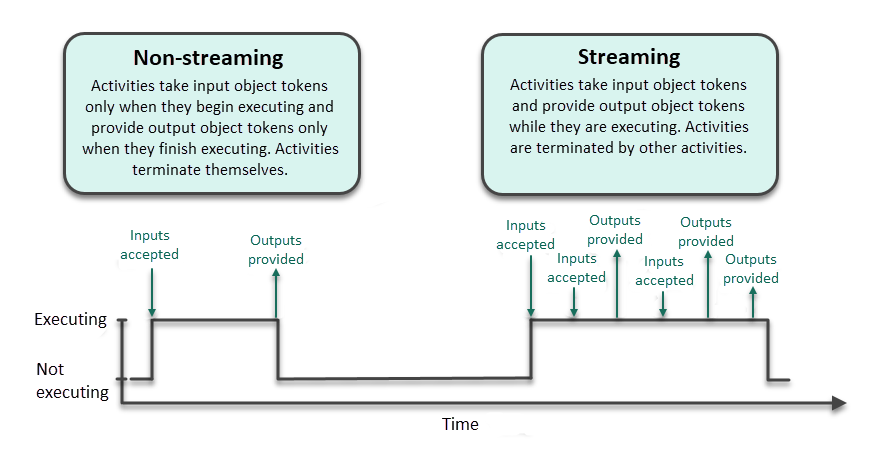
Magic Model Analyst 2021x supports the simulation of streaming activities when a system receives inputs and produces outputs even while behaviors continue to execute. As you can see in the example below, during simulation several actions can be executed simultaneously, and waiting tokens are displayed on action pins. Note that you can control the held token display in the Project Options dialog or Simulation Configuration properties.
An example of a streaming Activity.
This diagram shows the differences between streaming and non-streaming behavior execution.
Learn more about streaming Activity simulation >>
Displaying and Changing Runtime Values in Diagrams
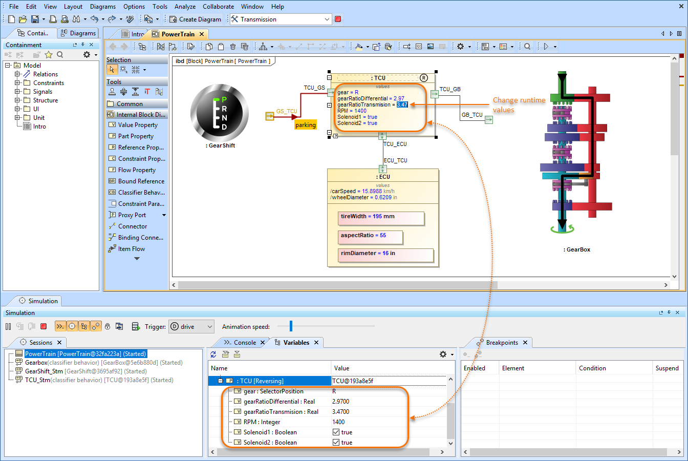
With Magic Model Analyst 2021x, monitoring and manipulating simulation information has never been easier. Now you can display runtime values of Parts in all diagrams based on a Composite Structure Diagram as shown in the figure below. But that is not all, you can also modify runtime values directly in a diagram the same way you do it in the Simulation window.
This sample model demonstrates how you can view and change runtime values of Parts directly in an Internal Block Definition Diagram.
Learn more about simulation information in diagrams >>
Displaying Active States in Diagrams
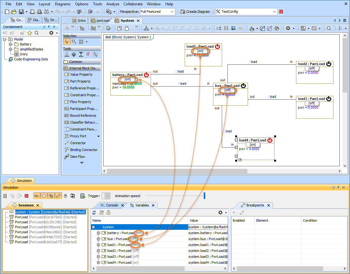
Now diagrams based on a Composite Structure Diagram display the active States of Parts when simulating a model. Active states are shown on the bottom of Part shapes the same way they are displayed in the Variables pane of the Simulation window. This new feature improves the readability of simulation information because you no longer need the Simulation window to see how active States change when executing your model.
In this Internal Block Definition Diagram, you can see that active States are displayed both in the Simulation window and on the shapes of initialized Parts.
Learn more about displaying active states >>
Displaying Active State Images
Make your model simulation look more illustrative and vivid by displaying active State images on Part shapes. You can do that by assigning an Image Switcher to the Simulation Configuration from which you execute your model or by applying an image to a State. When states change during simulation, state images change as well as displayed in the following figure.
Here you can see how active State images are displayed when simulating a model.
Learn more about displaying active state images >>
Displaying Flowing Information
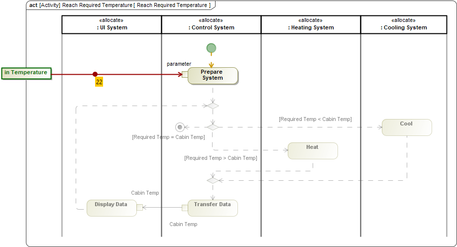
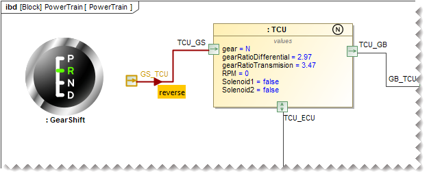
Magic Model Analyst 2021x allows you to see what information is flowing via paths that are animated during model execution. In Activity Diagrams, the flowing item is displayed as a bubble with a label showing the item name. In diagrams based on a Composite Structure Diagram, a moving triangle is shown on an animated path, as illustrated below.
The temperature value flowing in an Activity Diagram.
In this Internal Block Definition Diagram, you can see the neutral signal flowing from the GearShift to the Transmission Control Unit (TCU).
Learn more about displaying flowing information >>
Sending a Trigger in Diagrams
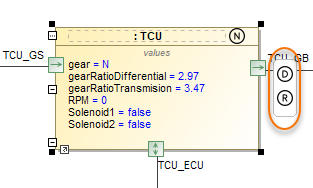
Now sending a trigger during model simulation is even more convenient because you can do it right from a diagram without using the Simulation window. You can send a trigger directly from a Part shape in all diagrams based on a Composite Structure Diagram. When it is possible to send a trigger, a special button is displayed on a Part shape after selecting it.
Simply click the highlighted button to send a trigger from a Part. If it is possible to send several triggers, the trigger list will be displayed for you to select from.
Learn more about manipulating simulation information >>
Reorganized Simulation Options
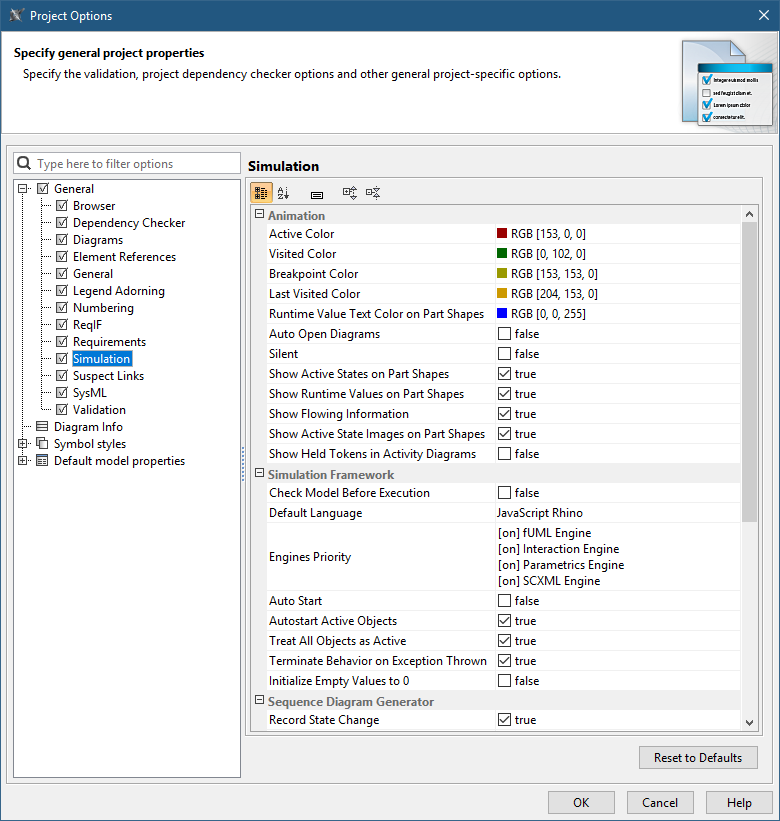
All Simulation options have been moved from Environment Options to Project Options for better user convenience, as it allows customizing simulation to fit a particular project. In addition, all simulation settings will be exchanged among users who collaborate on a server.
Furthermore, most of the Simulation Configuration options are duplicated in Project Options now, so you can specify default values for execution without using Simulation Configuration.
As you can see in this figure, all simulation options are now accessible in the Project Options dialog.
Animation Delay Logic
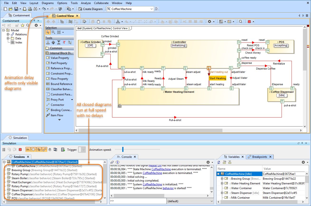
Animation delay affects only visible diagrams now. All closed diagrams and models run at full speed with no delays.
As you can see in the figure, animation delay affects only visible diagrams.
Interactive Guard Evaluation for STM and Sequence Diagrams
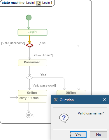
The guard conditions on transitions expressed in natural language cannot be evaluated, so the question dialog will be shown for you to choose. This behavior is consistent with decision nodes in Activity Diagrams.
When simulating this State Machine Diagram, a user is asked to choose whether a user name is valid or not.
Simulink Co-Simulation in Activity Diagrams
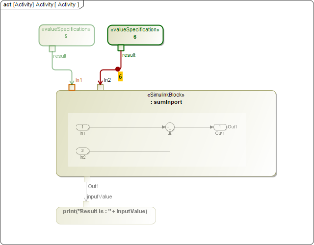
A Simulink *.slx file can be dropped into an Activity Diagram to create a «SimulinkBlock» Activity and a Call Behavior Action for it. If the file is attached to your project or stored in the project directory, Magic Model Analyst will be able to execute it with given input values and provide outputs to the action output pins.
In this Activity Diagram, a «SimulinkBlock» action has been created from a Simulink *.slx file.
Other
- A new -leaveprojectopen parameter has been introduced into the command-line interface.
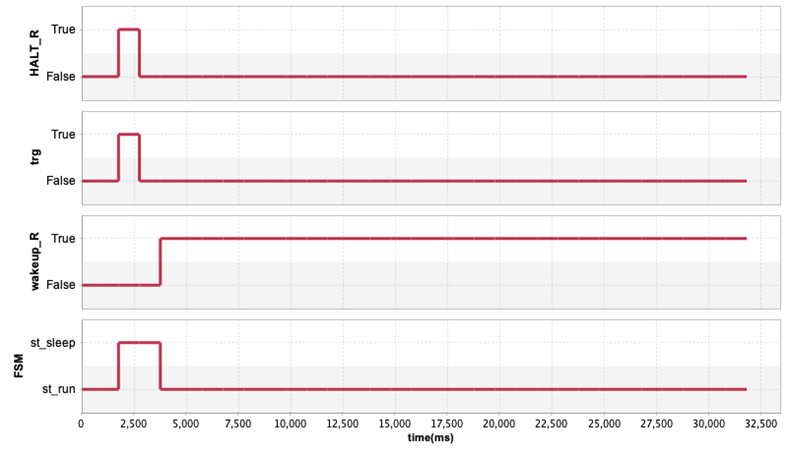
It allows leaving a project open for the next simulation if multiple property files are used in the simulation command. - Boolean and Enumeration values are represented in Timeline plots now.
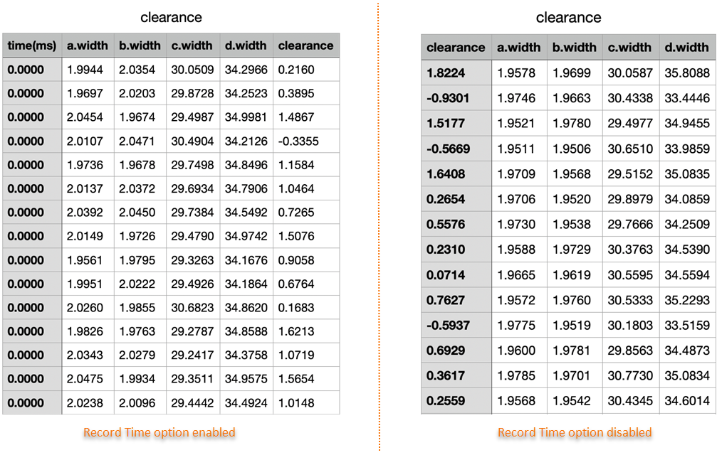
- A new Record Time option is added into CSV export configuration to be able to turn off the timestamp column when it is not needed, e.g., when recording Trade Study or Monte Carlo iterations.
Discontinued Integrations
- As of version 2021x, the integration with OpenModelica is no longer supported.
Key Issues Fixed
- Decision Nodes are now evaluated correctly when a decision Input Flow or Decision Input is available.
- State Machine Diagram simulation no longer freezes when an event is sent while in the entry or exit behavior of a state.
- A rare NullPointerException during Monte Carlo analysis has been fixed.
- The NumberFormatException in some trade study configurations has been fixed.
- The clock now supports the ns and μs time units.
News of earlier versions
