In a particular system or context where blocks are used, it is possible to add constraints on parts and constraint value ranges. To better explain how it works, see the following example of a car model.
A car model has front: Wheel and rear: Wheel. The diameter of the Wheel block is specified as diameter: Real value property. It is possible to add different constraints to different parts; e.g., the front wheel’s diameter is {diameter < 19} and rear wheel’s diameter is {diameter < 20}.
The following figure demonstrates a Car (block) along with the diameter of Wheel (constraints) applied to the rear, front, and spare wheel (part properties).
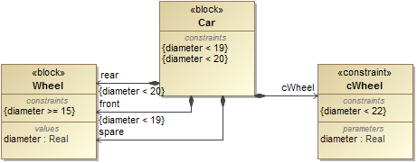
A sample model of constraints on part properties.
If the constraints of the block are applied to the part properties through another block with constraints inside, you will get the following results.
- The value ranges will be evaluated through all of the applied constraints. The constraints may reside in the part properties, main block, or constraint blocks. For example, front wheel {diameter >= 15, diameter < 19}.
- If a constraint fails during evaluation, a failure message will appear on the owned constraint; e.g., part properties, main block, or constraint blocks In the Simulation Console panel.
- In the Variables pane, the constraints applied to the part properties appear together with the constraints of its own part properties in {...}. Magic Model Analyst highlights failed constraints with a red background and opens the failure message in the tooltip of the applied constraint.
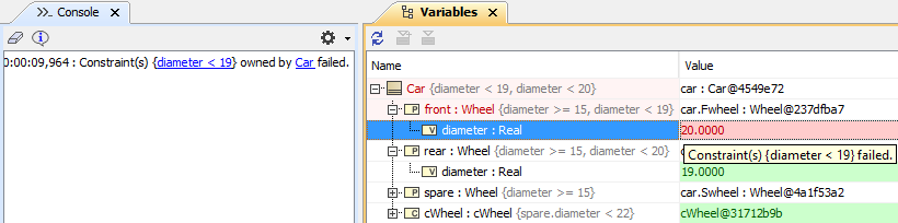
This figure depicts the constraints failure message in the Console panes and the details of failed constraints (in red background) that are applied to part properties front : Wheel in the Variables pane.