Released on: August 4, 2015
Integration with Cameo Enterprise Data Warehouse
We are proud to offer our users the integration with Cameo Enterprise Data Warehouse (CEDW), a new server for collaborative development and versioned storage of models. CEDW is envisioned and architected to provide significant future improvements in the areas of model-governance, model-analysis, and integration with third-party tools.

What are the differences between working with CEDW and MagicDraw Teamwork Server?
- Faster project opening*.
- Scalable server performance (server can be expanded to a cluster).
- Faster commits and updates of project changes.
- Faster team collaborations when server is located at MAN/WAN.
- Redesigned project composition of used projects.
- Model versioning with the built-in database.
- User authentication against LDAP server (multiple directories supported).
- Role-based access control (RBAC) with predefined set of roles for the server and project access management.
- Easier administration of the server and server-stored models via the web browser.
--
* After the project is cached locally, all later project loadings lasts only several seconds.


Validation Enhancements
Increase the performance of the modeling with visible diagrams validation mode, validation results marker bar, and diagram validation button. Find only compatible Ports/Interfaces in your model with Autowiring function or Enforce Ports Compatibility mode. Manage Ports much faster now.
Visible diagrams validation mode
Feel like validation of your model runs too slow? Going to stop it? Then switching to the visible diagrams validation mode is what you need! As a result, the active validation starts running only on elements displayed in one or more visible diagrams, which significantly increases the performance of the modeling tool.
Validation results marker bar
When your diagram is too large to be displayed all-over, it may become quite challenging to notice all annotated symbols it contains. In this case the new validation results marker bar is your true helper! It appears on the right side of a diagram pane, if the diagram contains annotated symbols.
The markers are shown even for the items that are not currently visible on the screen (you may need to scroll down to see them). The marker bar is shrunken to fit the screen and displays relative positions of annotated symbols on the axis of ordinates. Every marker is colored according to the violation severity.
You can click a marker to select the annotated symbol or move the mouse over the marker eye (at the top-right corner of the diagram pane) to see the summary of the diagram validation results.
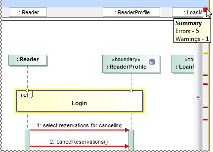
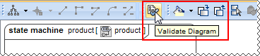
Diagram validation button
Need to validate only a small portion of the model you just have modified in a diagram, table, matrix, or relation map? Click the new button on the toolbar of this diagram, table, matrix, or relation map to run the validation only there.
New rules and specifications
From now on
- Validation reports an error, if an Opaque Behavior or Activity Parameter Node contains more than one return Parameter.
- The warning message “Too few tag values” indicates which tagged values failed the procedure. You no longer need to look for the particular undefined tagged values manually.
Ports/Interfaces compatibility
It's easier to create compatible connectors in the Internal Block Diagram using:
- Autowiring function that analyzes and finds compatible Ports/Interfaces. As a result it creates connectors automatically! It works for entire diagram or individually selected Parts or Ports.

- Enforce Ports Compatibility mode that restricts connections and highlights compatible Ports only.

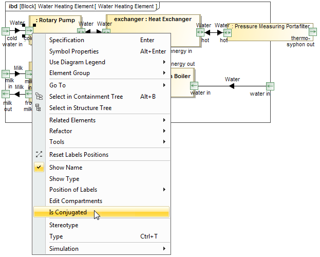
Simplified Port's management
- Reverse Port direction much faster by changing Is Conjugated value from the shortcut menu.
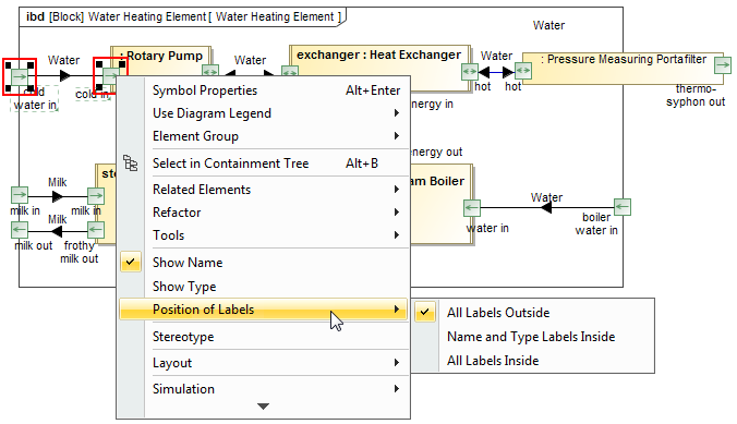
- Now you can adjust the position of labels of several Port shapes at once. In earlier versions this was possible only for a single shape.
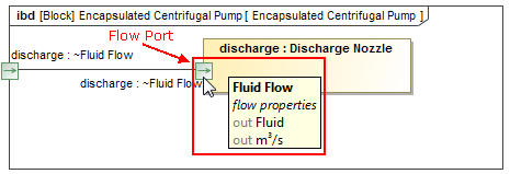
- From now on moving the pointer over the Flow Port displays a ToolTip that shows Flow Specification properties.
Completely Reworked Model Comparer and Upgraded Merge
Now you can easily track modifications by comparing different project versions, effortlessly review changes in the difference tree, change details panel, and on diagrams, as well as conveniently save everything to your documentation.
New look
Due to the new appearance, model comparer is now more user-friendly, and provides more explicit information about changes without causing confusion.
A single difference tree, instead of the previous two, helps the comparer to provide a clearer visual structure of the changes made. An easily readable legend provides the number of differences for quick overview, and more detailed information is provided in the Change Details panel.
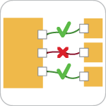
Reviewing diagrams
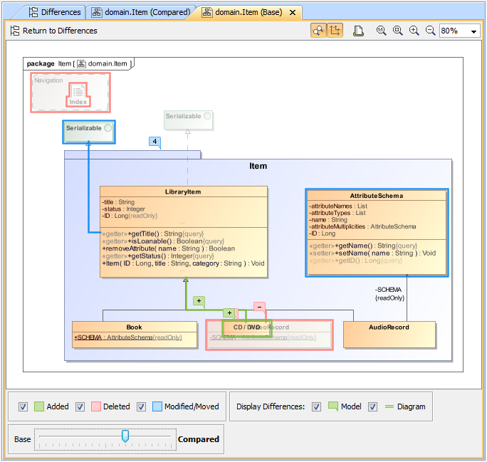
Forget looking at diagrams for hours without actually knowing what has changed in a model or trying to track the minor symbol movements – that is now in the past. The improved diagram Difference Viewer window was introduced into both model comparer and merge to enable users to notice, distinguish and filter modifications instantly.
Recognize the nature of each modification – color coded lines and flags allow quickly distinguishing between addition, modification/move or deletion changes. Too many colors, lines and flags in one place? Filter to show only model/symbol changes, or a certain type of modifications. Each model change in a diagram is marked with a flag and by simply clicking it you can instantly navigate to the model tree to review the changed details.
No more switching between different diagrams versions – a new slider provides an animated view of how your diagrams changed with every modified version.
Extensive reporting
Finished reviewing changes and wish to see them on paper? We made it easy – simply export all the diagrams with visible changes to a Microsoft Word document using one of two predefined templates – Diagram View or Full View for a more detailed overview, including the full tree with all dependent changes. Need less information? Create your own customized template and generate reports of any desired depth and scope.
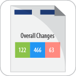
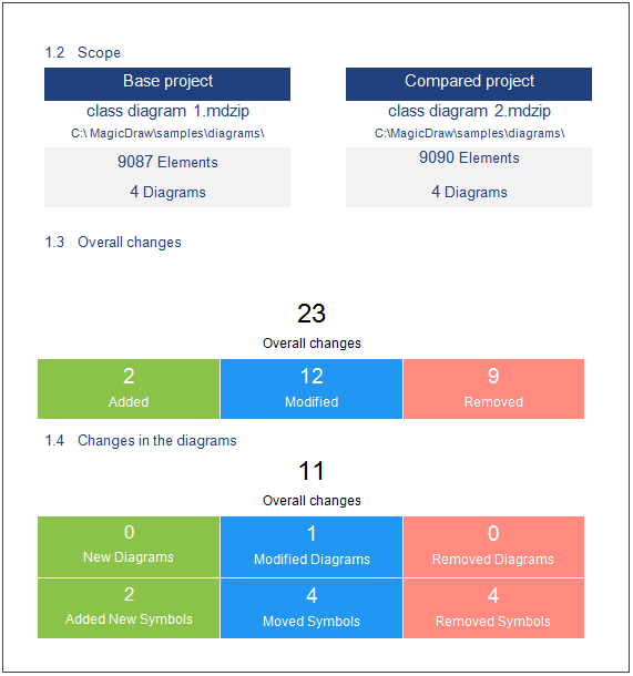 The illustration displays a fragment of the Project Comparison Report.
Merge upgrades
A minimized toolbar, more comprehensive legend, and a simplified two-way merge appearance give the Merge window a nice make-over. Improved representation of changes in diagrams and reporting options provide even more power to the project merge.

Interchange of Requirements via ReqIF
From now on, an interchanger of Requirements via ReqIF files are improved with requirements export oppurtunity, requirements without specifications import, Reqtify, pre- and post- processing script support!
Exporting requirements via ReqIF
We are very happy to introduce full interchange – import and export – of requirements via ReqIF files. ReqIF is the standard, easiest, and quickest solution for interchanging requirements using different tools. HTML formatting, images and hyperlinks interchange are supported. You can choose to export project elements or specifications. Advanced users can create automated exports and scheduled exports from Teamwork Server projects.
Interchange with Reqtify
For your convenience, we added Reqtify support to the current list of supported ReqIF flavors to interchange with. Reqtify by Dassault Systems is a requirement interchange, traceability, and impact analysis tool.
Reqtify provides an interface to requirement-related information in a wide variety of data formats, document types, and file formats from the Dessault Systems products family, as well as from common ones, such as MS Office files.
Note: ReqIF support in Cameo Requirements Modeler enables requirements interchange between requirements management tools, such as IBM DOORS 9.4, 9.5 and 9.6, IBM DOORS Next Generation, PTC Integrity, Polarion, Siemens Teamcenter, and Dassault Systems Reqtify.
Pre- and Post-processing on import/export
Pre- and post- processing script support for requirements export and import allows basically any kind of requirements modification and enables you to create custom mapping on requirements interchange through ReqIF.
Importing Requirements without specifications
Importing requirements without specifications is now possible. This is mostly the case with requirements exported from IBM DOORS Next Generation, which supports export and import of only plain requirements.
Increased Modeling Efficiency
We are pleased to introduce editable derived SysML properties and tags, Value type as Reals, faster QUDV library access, improved Behaviors property group, automated management of Use Case subjects, smarter diagram layout, transparency of unconnectable shapes, relation map enhancements, and many more features save modeler's time and allow focusing on what to model, but not how to model and keep the result well-formed.

Editable Derived SysML Properties and Tags
Now you can edit the derived SysML properties/tags, such as Allocated From, Allocated To, Satisfied By, Verified From, Satisfies, in Specification window, tables, and relation maps.
ValueTypes as Reals
From now on, all ValueTypes are interpreted as Real numbers by default if it is not specified otherwise. The LiteralReal is used for default value or Slot Value of the value property.
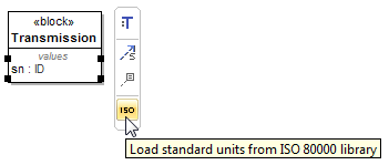
Faster QUDV Library Access
You can access the full ISO 80000 library for more standard units and value types much faster now by clicking the ISO button.
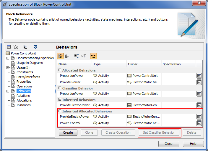
Improvements in Behaviors property group
From now on all inherited allocated behaviors are collected and displayed under the Inherited Allocated Behaviors category. Also you can change Classifier Behavior simply by clicking the new Set Classifier Behavior button.
Automated management of Use Case subjects
From now on, dragging a Use Case onto a Class in a diagram sets that Class as the subject for the Use Case.

Having a Use Case with the subject jump-starts the creation of Swimlanes in the Activity diagram owned by that Use Case. In this case, you can select the subject properties you wish to be represented by the Partitions of that Swimlane.

Smarter diagram layout
- Our enhanced Composite Diagram Layout makes working with composite diagrams even more hassle-free – a dynamic shape spacing approach within layers has been implemented, label layout has been improved and support for conveyed labels added.
- Port placement on diagram frames has been improved to better satisfy your modeling needs when using Composite Diagram Layout.
- Parts no longer overlap each other after you choose to display them.
- The new Shape Order option coming with the Hierarchic Layout allows you to specify the order of laid-out shapes; thus, making the creation of Requirement diagrams more convenient and time-effective. Now you can arrange your shapes by name or by numbering.
- A new, separate Grid Layout has been created to enable you to layout elements in a COMPACT grid. Its options allow ordering elements by a defined comparator, and also the definition of aspect ratio that the layouter can work on. The Grid Layout has the Make preferred size option; if true, elements are resized to the smallest possible sizes, if false, elements remain of the same sizes they are. The Minimal shape distance option determines the distance between shapes.
Transparent unconnectable shapes
Forget about considering which shape is suitable for connection! From now on all the shapes that cannot be connected with the selected shape become less visible on the diagram pane.
![]()
You can specify the transparency of unconnectable shapes by changing the Transparency of Unconnectable Shapes property value in the Environment Options dialog, the Diagram property group.
Relation Map enhancements
The Relation Map can now display
- Element numbers after you click the Option button on the Relation Map toolbar and then select Show Element Numbers.
- Standard and custom subtypes of the selected element type after you choose the element type and then select the new Include Subtypes check box in the Select Element Type dialog.
Plus, you're welcome to use the zoom buttons directly from the relation map toolbar!
Miscellaneous
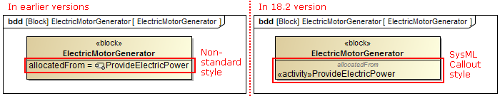
The SysML Callout Style is now applied in the Compartment area of the Block, Requirement, Part, and Action for better compliance with SysML specification. To return the non-standard style, set the Apply SysML Callout Style property value to false in the Symbol Properties dialog.
The root package in the Model Browser is now renamed from Data to Model in the newly created SysML, Simulation, and Requirements projects.

- A new Display Parts button has been added to the smart manipulator toolbar, making access of the command quicker.
- Due to the newly introduced symbol property Inner Elements Sort Mode, you can now choose how to arrange your Package inner elements. Keeping the default selection No Sorting leaves the elements sorted by the date of their creation, whereas selecting By Name sorts Package inner elements alphanumerically.
- Converting a State to a Composite State no longer requires you to manually create a Region inside that simple State. The conversion is carried out by simply dragging a vertex on a simple State symbol.
- We have updated the Project Options and Environment Options dialogs for your convenience – now when you open either of them, you see the General options grouped into sub-categories with links in the right side of the dialog. This saves you time from guessing where a certain option is, also it makes access to those options easier – simply click the link, and the chosen option sub-category will be selected in the tree and opened in the right pane.
Other News
Online documentation
It‘s our pleasure to announce that as of 18.2 FR, we are starting to move all our actual documentation online – to a single, user-friendly platform with advanced searchability.
For a limited time, you might notice this migration is in progress. This means that:
- At first, only 18.2 new features' documentation will be available in the new site.
- Temporarily, there will be no offline documentation for the 18.2 FR.
- Offline documentation accessible via Cameo Systems Modeler is up to 18.1.
- Context-sensitive help (F1) will reference to 18.1 documentation.
We plan to provide the complete online documentation until the release of the next LTR.
We'd like to apologize for any inconvenience this migration may cause. Your patience and trust in us is what inspires us to look for even better solutions for our clients!
Optimization for high resolution displays
Now OS X users can take full advantage of a long-awaited Retina display support, allowing those who work with higher resolution screens to see more detail in diagrams and enjoy sharper icons in the interface.
Those who use Cameo Systems Modeler for Windows and Linux with high resolution screens will definitely notice the initial steps taken towards full HiDPI support – you can now benefit from a significantly better overall visual quality, including proper scaling and increased sharpness of icons.
Discontinued compatibilities and dropped integrations
- Windows XP is no longer supported. You may still use Cameo Systems Modeler with Windows XP, however, full functionality of the tool is not ensured.
- Cameo Systems Modeler 18.2 integration with CVS is not supported.
- EMF-based UML v1.0 projects are no longer supported.
If you need to continue using these file formats or deploying these integrations, you are welcome to use Cameo Systems Modeler 18.1 or earlier.
Eclipse UML 2.5 model data export
The Eclipse UML 2.5 model data export from and import to Cameo Systems Modeler is now fully supported.
All available Eclipse UML 2 XMI formats – Eclipse UML 2 v2.x/v3.x/v4.x/v5.x/ XMI – are now listed under a single File > Import From / Export To command group Eclipse UML 2 XMI File.
Open API changes
OSGi framework
From now on, MagicDraw uses the Eclipse OSGi framework, one of the leading technologies for clean architecture and dependency management between components. Migration to OSGi was necessary for MagicDraw integration with Cameo Enterprise Data Warehouse.
MagicDraw and all plugins are now wrapped into a single OSGi bundle. This change in most cases has no impact for MagicDraw plugin development, since development principles remain the same as before.
However, there are some changes in starting MagicDraw.
Changes in starting MagicDraw from the command-line
com.nomagic.magicdraw.Main was deprecated. Use com.nomagic.osgi.launcher.ProductionFrameworkLauncher to start MagicDraw in this case. Additional java properties must be passed to this new launcher.
For more information, see Specifying batch mode program classpath and required system properties.
Changes in starting MagicDraw from another Java application
To make MagicDraw classes accessible, run this Java application inside the OSGi framework too. Use com.nomagic.magicdraw.core.Application#start(java.lang.String[]) to start MagicDraw in this case.
For more information, see Starting MagicDraw or other modeling tool as part of another application.
Integration with CEDW and changes in project structure
Due to MagicDraw integration with a new server, Cameo Enterprise Data Warehouse (CEDW), a new type of project was added. From now on, we have three types of projects: local project, Teamwork Server project, and CEDW project.
There is a great chance that plugins won't work correctly with CEDW projects, since this type of project (in contrast to local and Teamwork Server projects) can have many root elements. The root element of each used project becomes a root element in the main CEDW project. Thus, please review the existing plugins.
For working with multiple root models, a new API was added into the com.nomagic.magicdraw.core.Project:
- public java.util.List<com.nomagic.uml2.ext.magicdraw.classes.mdkernel.Package> getModels ()
- public com.nomagic.uml2.ext.magicdraw.classes.mdkernel.Package getPrimaryModel ()
public com.nomagic.uml2.ext.magicdraw.classes.mdkernel.Package getModel () was deprecated.
HiDPI monitors support
Since the loading of different resolution icons by monitor DPI was implemented, the new class is introduced for loading multi-resolution icons:
- com.nomagic.magicdraw.icons.IconsFactory
Element lookup API
Elements lookup API was refactored and cleaned. Two new utility classes were added:
- com.nomagic.magicdraw.uml.Finder - provides the API for element lookup by simple name, qualified name, metatype, scope, and level of depth in the model structure.
- com.nomagic.magicdraw.uml.ClassifierFinder - provides the API for UML Classifiers lookup and creation by simple or qualified name and metatype.
com.nomagic.magicdraw.uml.ElementFinder was deprecated.
Return types
Return types were changed for the following methods:
- com.nomagic.magicdraw.core.ProjectUtilities.getAttachment(IProject, IProject)
- com.nomagic.magicdraw.core.modules.ModulesService.UsedViaReadOnlyAutomaticUsageException.getOffendingUsages()
- com.nomagic.magicdraw.teamwork2.ITeamworkService.getVersion(Project)
- com.nomagic.magicdraw.teamwork2.ITeamworkService.getVersions(ProjectDescriptor)
UML metamodel changes
Multiplicity of the following member ends of meta-associations in UML metamodel was changed from [1] to [0..*]:
- Association.get_clearAssociationActionOfAssociation
- Classifier.get_readExtentActionOfClassifier
- Property.get_readLinkObjectEndActionOfEnd
- Property.get_readLinkObjectEndQualifierActionOfQualifier
- Trigger.get_replyActionOfReplyToCall
UML metamodel API was changed according to these changes.
File format changes
- The "parameter" reference was removed from xmi:Extension for Pins and ValueSpecifications. It does not exist in UML metamodel.
- The "syncElement" reference was added to xmi:Extension instead of standard reference. It is not a part of UML standard metamodel.