On this page
Introduction, overview, and when to use
When applying the variant management/product line engineering methodology to the system models, one case frequently arises: replacing one part with a different (but compatible) part depending on the selected configuration/variant. This can be a structural part – i.e., part of the block, or it could be a behavioral part - some action in the activity.
The important aspect of this replacement is that connectivity needs to be preserved. Whatever inputs and outputs were connected to the original part needs to be connected to the analogous inputs and outputs on the replacing part. This applies to connectivity in both structural aspects - connectors, connecting parts in the Internal Block Definition diagrams, and behavioral aspects - data flows, providing inputs and outputs of the action in the activity.
Before the introduction of this new variation point kind, the following two methods were available:
- Using existence variation points
- Using Element Property variation points
Using existence variation points, the user would model multiple parts in his system, each of the parts of a different specific type. And then, those parts would be decorated with existing variation points, with such expressions as to leave only one of these compatible parts under any configuration circumstances described in the feature model.
This approach suffers from a lot of clutter in the diagrams, and it distorts the semantic meaning of the system – thereby making the model hard to understand. The car never has four engine parts, even if four variants of the engine are available and are being used for different configurations.
Using the Element Property variation point, there would be only one part, and the element property variation point would be applied to it, changing the type of the part to the necessary specific type (let’s say - use one of the four specific engine blocks as the type of the engine part).
This approach is semantically better than the previous one but suffers from a different problem. Usually, the specific types do have different (albeit similar) ports. E.g., a gasoline engine has a gas input port, while a diesel engine has a diesel input port. If the type of the part is being changed by the element property variation point, then the previous ports displayed on that part are no longer valid. Therefore any of the connectors connecting to those ports are no longer valid. To achieve model validity, any connectors attached to the ports of the original block must be re-routed to the new ports. This could be done in principle (again, using many additional Element Property variation points on the connector ends), but this was so complicated and clumsy as to be hardly usable.
Therefore a new kind of variation point is being introduced – Replace and Rewire. This variation point kind applies to the parts (structural modeling case) and actions (behavioral modeling case). This variation point kind functions similarly to the Element Property variation point, but in addition to changing the part type or behavior of CallBehaviorAction (the “Replace” part), it also rewires the connectors (structural modeling case) and object flows (behavioral modeling case), connected to the ports of the part and pins of the action (the “rewire” part).
Being a somewhat complex variation point, it needs some preparatory modeling work before it can be properly used. Please read the chapters below about the preparatory phases.
Preparatory phase - Initial model setup
To make use of the Replace and Rewire variation point, the model needs to be properly set up.
Let’s say we have a collection of blocks, all different but similar and performing similar functions. For example, here is a collection of engine blocks:

A collection of engine blocks, used for example build-up.
Our task is to create the multi-variant model of the system, such that a part is typed by one of these blocks, depending on the configuration. In the example case above, we are building a car such that depending on the chosen configuration, one of these engines is used.
As a starting point, there has to be a model element for a common block – capturing all the generic aspects common across all the concrete block types.
This common block is then used to build up the multi-variant system. It can be used in the Block Definition and Internal Block diagrams normally – as a type of part, building up the larger system.
Block Definition diagram of the Car model, using abstract Engine block as a Part.
This common abstract block must have a number and type of ports, such that for each port of the concrete blocks that we want to use, there is an equivalent corresponding port in the abstract block. In the example above, we see that the abstract Engine block has four ports, which have equivalent ports in each of the concrete blocks that we want to use.
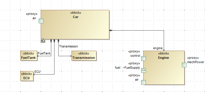
These ports of the abstract, common block can then be used to establish connectivity of the varying system part to other parts of the system, using normal connectivity means (i.e., connectors):

Multi-variant part, connected to other parts of the system.
This abstract, common block can carry additional information using the same system modeling principles. It can:
- Have internal structure and value properties.
- Be connected to other model elements (e.g., Satisfy some requirements).
- Have constraint blocks.
- Have its’ own behaviors, etc.
Place only that modeling information in this block, which is common across all the concrete blocks that you want to use in its place.
This paragraph above describes the model setup for the structural modeling case. Analogous principles need to be followed for building up the behavioral modeling case – just for the different kinds of model elements:
- Instead of blocks, use behaviors (note: the most common case would be to use Activities, but using other kinds of behaviors – State Machines, Sequences - is also OK)
- Instead of parts, use actions (technically: CallBehaviorActions)
- Instead of the ports, use parameters and pins. Note: this is where there is a slight difference – for structural modeling, there is only a port on a block, and the part does not have any additional model elements (part is just “showing” the ports that are on the block), while for behavioral modeling there are two different model elements – parameter on the behavior, and pin on the call behavior action. However, this difference is only technical (it stems from the underlying UML model) and does not affect the usage principles of the Replace and Rewire variation point.
- Instead of connectors, use object flows in activities to express the Action connection to other actions and data flow into and out of it.
Preparatory phase - Type Compatibility Declaration, matrix
Once the common general block is created, compatibility between it and the concrete and specific blocks that can take its place must be declared in the model.
This can be done in two ways:
- Using “natural” UML means – Generalization relationships
- Using an auxiliary mechanism – Compatible relationships (this is a UML Dependency with a «Compatible» stereotype applied).

Using UML Generalization relationships to express compatibility between the general Engine type and specific engine types.
 Using the custom Compatible relationships to express compatibility between the general Engine type and specific engine types.
Which method to use depends on the circumstances. The “natural” way is usually better because more of the tool mechanisms can understand and use it – it has a meaning besides just using it.
However, in some cases, it is not possible to use generalizations. For example, if the specific types reside in a separate module (library of parts), it is impossible to add a generalization between them and the general type because the specific types are read-only, and the generalization must be placed into a specific type according to UML rules. In such cases, use a Compatible relationship. As it is based on UML Dependency, its placement is not so strictly prescribed by the UML standard.
There are many ways in which these relationships can be created. They can be created using ordinary means provided by the tool (in Class, Block Definition diagrams), but an additional convenience is provided for this – a predefined Type Compatibility Matrix.
To create the Type Compatibility Matrix
- In the containment tree, select a package or another model element wherein the matrix will be stored.
- In the main toolbar, click the Create Diagram button.
- Expand the Product Line Engineering section.
- Click the Type Compatibility Matrix icon.
A matrix will be created. This is a normal Dependency Matrix but with predefined Row/Column Element Types and Dependency Criteria (allowing both Generalization and Compatible relationships to be used).
The user will usually need to adjust the row and column scopes. The columns should contain your general types, while the rows – the specific ones. This is done in the matrix header, Row Scope, and Column Scope fields.
The single matrix can express compatibility between many of the compatibility sets. So, the single matrix can show compatibility between the engine blocks and between, the transmission blocks and between some behaviors, etc. The only contra-indication to building large matrices is clutter, so if the matrix grows too big, it can be partitioned into several matrices.

Type Compatibility Matrix, showing compatibility between Engine blocks and RegulatePower activities.
To declare that a particular row element is compatible with a particular column element, double-click the corresponding intersection cell. The user will be asked which kind of relationship to create: Generalization or Compatible (see above for guidance on which one to create under what circumstances).

Declaring compatibility between the general Engine block and specific EcoBlue 2.0L Engine block.
To remove the declaration, double-click the occupied cell. The relationship displayed in that cell will be removed from the model.
Preparatory Phase – Input Output Compatibility Declaration, matrix
In addition to specifying the compatibility between the general block and specific blocks, compatibility between the ports of those blocks must also be specified.
This can be done in two ways:
- Using “natural” UML means – using the redefinedElement field of the Port.
- Using an auxiliary mechanism – Compatible relationships.
To use the first method, if the ports on the specific block are not yet created, you can use the Redefine button in the Ports/Interfaces section of the specification window of the specific block. This button creates the port in the specific block and links it to the port in the parent block in one go:

Creating a port in the specific block, which redefines the port in the general block.
If the ports are already created in the specific block, then redefinition can be specified by opening the specification window of the port on the specific block, switching to the All properties mode, and filling in the redefinedPort field with the port on the general block.

Manually specifying port redefinition between a port in a specific block and a port in the general block.
Note that the “natural” mechanism for port compatibility declaration can only be used if the compatibility between the owning block types is also declared using the “natural” mechanism (i.e., UML Generalizations). Otherwise (if the compatibility between blocks is expressed with a Compatible relationship), the Compatible relationships must be used between ports as well.
A convenient way to declare port compatibility is to use a predefined Input Output Compatibility Matrix.
To create the Input Output Compatibility Matrix
- In the containment tree, select a package or another model element wherein the matrix will be stored.
- In the main toolbar, click the Create Diagram button.
- Expand the Product Line Engineering section.
- Click the Input Output Compatibility Matrix icon.
A matrix will be created. This is a normal Dependency Matrix but with the predefined Row/Column Element Types and the Dependency Criteria (allowing both redefinedElement and Compatible relationships to be used for compatibility).
The user will usually need to adjust the row and column scopes. The columns should contain your general types, while the rows – the specific ones. This is done in the matrix header, Row Scope, and Column Scope fields. The ports in those types will be shown in the matrix, and it is the ports that need to be connected to declare compatibility.

Input Output Compatibility Matrix showing compatibility between generic Engine ports and ports of specific engine types.
The same principles apply to specifying the relationship as for other dependency matrices. Doubleclick in the empty cell to create the relationship – thereby expressing compatibility between the port of the row and the port of the column (you will be asked which of the two criteria you want to use). Double-click the filled cell to remove the underlying relationship.
This paragraph above describes the model setup for the structural modeling case. Analogous principles need to be followed for building up the behavioral modeling case – just using Parameters of the Behavior (usually - Activity) instead of the Port of the Block. However, there is no “natural” UML way to express compatibility between the parameters. Only the “Compatible” relationship mechanism can be used.
Specifying Replace and Rewire Variation Point
After the preparatory work is done (see previous paragraphs), Replace and Rewire Variation Point can be applied.
For the structural modeling case, Replace and Rewire variation point is applied on the part property (N.B. – not on the block) whose type needs to be changed. In the Internal Block Diagrams, that would be the box representing the part. In the Block Definition Diagrams, this would be the association end.
For the behavioral modeling case, Replace and Rewire variation point is applied to the action (specifically - CallBehaviorAction) that is calling the behavior which needs to be changed. These actions are most of the ovals in the Activity diagram (note – some ovals can be actions of different flavors – open specification window to determine what type of action you have).
Right-click the necessary element (if in the Block Definition Diagram, right-click the end of the association, not the middle!) and click Variants Modeling > Replace and Rewire. Replace and Rewire Variation Point will be created and applied to the target element. This is indicated by the appearance of the blue bubble in the top right corner of the shape of the model element.

Replace and Rewire variation point creation.
This variation points works similarly to the already existing Element Property variation point, except that it does more.
Some of the information on the variation point is automatically filled during variation point creation. You can see this information in the specification window of the created variation point:
- The Property Name field is set automatically. When Replace and Rewire variation point is applied on a part property, this field is set to type. This means – the variation point will be adjusting the type field of this part property model element. When Replace and Rewire variation point is applied on a call behavior action, this field is set to behavior. This means – the variation point will be adjusting the behavior field of this action model element.
- The Element Value Specification table is partially filled. This table is filled using the compatibility information (see previous chapters for information on specifying type compatibility). For the structural modeling, a property type is taken, and compatible types of this type are listed in the value specification table – one compatible type for each row. For the behavioral modeling case, the behavior of call behavior action is taken, and compatible behaviors of that behavior are listed in the value specification table – one compatible behavior for each row.
Note: if the set of compatible types/behaviors changes after creating the variation point, the element value specification tables are NOT updated automatically. After the compatibility information update, the user needs to review his variation points and manually update the tables – adding/removing/changing rows IF necessary with the Create/Delete buttons.
To fully specify the variation point, additional information must be specified.
The influencing feature(s) need to be declared in the Feature Impact panel in the specification of the variation point. This can be one feature from the feature model or multiple features. They are added by using the Add button in the panel.
After adding the influencing feature with Add button, the specification window shows the specification of the FeatureImpact relationship created by the Add. To get back to the specification window of the variation point, press the Back button at the bottom of the Specification window.
- Additional information is needed in the Element Value Specification table. Namely condition under which a particular row is selected needs to be specified. See below.
Declaring feature impacts:

The user declares feature impacts for the Replace and Rewire variation point.
Filling in the Element Value Specification table:
 Some data is pre-filled by the tool during the creation of Replace and Rewire variation point.
For each row in the table, the user needs to specify one of the two:
- Either the Expression In this case, the user needs to click the … in the field, and the expression editor will be opened. Pick the expression language (usually the same scripting language is used for variation points across the project – JavaScript Rhino or Jython – consult the company policy) and write the expression using the variables indicated in the header of the expression. Each feature declared in the feature Impact table is accessible as a variable in the script expression. The expression must return true for the condition under which the Element of that particular row will be used for the varying part type/action behavior.
- OR the Test Feature, Test For This simplified method can be used IF the variation point depends on the enumerated feature. In this case, select the feature in the Test For dropdown, and select the appropriate value from the available ones in the Test For dropdown. The Element of the row in this table will be used when the feature (indicated in the Test Feature) value in the selected configuration is set to the value indicated in the Test For.

Influencing features are accessible as variables in the variation expression.
This is how the fully specified Element Value Specification table looks:

The user declares variation conditions for Replace and Rewire variation point.
This table establishes a CASE statement for the variation point:
- IN CASE (condition of the first row is true) THEN use the Element of the first row as a type of the varying part/action of the varying behavior
- IN CASE (condition of the second row is true) THEN use the Element of the second row
- …
This case statement is processed from the top down, and the first condition, which evaluates to true, gets activated. If none of the conditions are true for the selected configuration, the type of the part/behavior of the action remains unchanged.
How the Replace and Rewire variation point works
Once the Replace and Rewire variation point is fully set up, its effects are visible during variant preview and variant realization transformation (illustration here after realizing diesel variant):
 Variant realization result of the Replace and Rewire Variation Point.
Observe how the ports are also replaced with the compatible ports of the target type. These are the different ports than the ones in the original – as seen by replacing the fuel port with a diesel port. The air, control, and mechPower ports in this example have the same names in the original (before replacement) as in the replacement; therefore, their replacement is not so visually obvious.
When realizing a particular configuration, all variation points in the realization scope are evaluated. For Replace and Rewire variation points, their element value specification table is processed row by row. Row expression is evaluated (if the Expression field is filled for that row), or the indicated feature (specified in the Test Feature of the row) value in the configuration is compared with the needed value for that row (specified in Test For of the row). If the row expression returns true OR the feature value matches the needed value, the row is selected for activation. The Element field of that row is taken and written into the appropriate field of the variation point target–type field of the part property (for the structural modeling case) or behavior field of the action (for the behavioral modeling case). This is the “Replace” part of this variation point kind.
In addition, all the connectors connected to the ports of the part (for the structural modeling case) and all the object flows connected to the pins of the action (for the behavioral modeling case) are examined and re-wired if necessary. The information from the Input Output Compatibility matrices is used for that. Let’s say the variation point replaces the base block B with the special block S, where S is the block coming from the Element field of the selected row from the element value specification table, the variation point. Let’s say the I/O compatibility matrix indicates that port P of block B is compatible with port Q of block S. In that case, all the connectors connected to port P of the variation point target part will be reconnected to port Q on the part. Port P will be removed from the diagram(s) displaying the part, while port Q will be placed geometrically in the same place where port P was on the diagram(s). This is the “Rewire” part of this variation point kind. The object flows, connecting to the pins of the call behavior actions, are handled analogously.
There is additional functionality for port removal (and pin removal – for the behavioral modeling case). IF the I/O compatibility matrix for some port P of block B does not specify the compatible port Q on the compatible block S (and if S does not inherit the port P), this means that port P does not exist on S, and it needs to be removed during the variant realization, and any connectors connected to such a port will be removed as well.

Illustration of the port being removed during the rewiring.
In the example above, the chosen configuration specifies the antique engine type for the engine part. This engine type does not have a control port, and there is no compatibility mapping specified for the control port of the generic Engine type. Therefore the control port will be removed during the variant realization, with the connectors connected to it, and this is indicated in the example above.
Note that this port removal capability is only possible IF compatibility between the blocks is expressed using the Compatible relationship and NOT the Generalization (refer to the chapters about compatibility specification for the description of these two methods). If generalization is used, then the specific block always inherits the parent’s ports, and there is always a needed port on the specific block, so removal never happens.
Feature Impact Relation Map
Feature Impact relation map is a special predefined relation map for showing the MBPLE feature model in an easily navigable form and also showing the system model elements affected by those features.
To create this relation map
- In the containment tree, select a package or another model element wherein the matrix will be stored.
- In the main toolbar, click the Create Diagram button.
- Expand the Product Line Engineering section.
- Click the Feature Impact Relation Map icon.
A map will be created. Additionally, a starting element is necessary for the relation map – a context. For this relation, the map starting element has to be a root feature group of your feature model (i.e. class, having the «RootFeatureGroup» stereotype applied). After creation, the owner element of the map is used as a context, but this is usually not the needed root feature group, so it needs to be adjusted.
To set the context, select your root feature group in the containment tree and drag and drop it into the map. Alternatively, you can use the Context field in the header of the relation map.
After the proper context is set, the map will be built automatically. You can navigate it by expanding the nodes of interest to drill down into one or the other area of your feature model. You can also auto-expand the relation map tree to the predefined depth by using the Depth input field in the toolbar of the relation map. After setting the depth, press the Refresh button (directly to the right from the depth input field). For any model element you navigate in this map, you can select that element in the containment tree (by right-clicking it and clicking Select in Containment Tree in the context menu) or open the Specification window (by double-clicking) to further investigative actions. A useful investigative feature is selecting the given element in the diagram where it is used. This is done by right-clicking the element and clicking Go To > Usage in Diagrams > some diagram (note that for finding a model element in the generic tables, relation maps, and dependency matrices, you need to click Other Diagrams).
The Feature Impact relation map shows the following related elements:
- The root feature group itself. This is the starting point of the map
- Any of the features in it. This is shown in the relation map with Black arrows.
- If the feature is composite (i.e. its type is a class with «FeatureGroup»), then the subfeatures of it. This is shown in the relation map with Light Grey arrows. This way, the relation map shows the entire feature tree to the full depth.
- If the feature is enumerated (i.e. its type is an enumeration), then the enumeration literals are also shown. This is shown in the relation map with Cyan arrows.
This is also the case when the feature is a composite feature, with the feature type having subclasses. In this case, the subclasses are connected with the Cyan arrows
The above relation map rules build up the relation map of features. But this relation map continues further – showing the model elements affected by those features (displaying feature impact relations).
The color of the arrows used to connect these elements depends on the selection of the current configuration (in the Preview field of the main Variants toolbar). If no configuration is selected, all the arrows will be Grey – undecided. After configuration is chosen in the main toolbar, refresh the relation map to show the feature impact arrows in new colors.
The feature impact arrow can be solid (SI indicator in the relation map legend; SI is the abbreviation for Single Impact) if the feature is the sole governing feature of the model element. If the element is governed by a combination of several features, the arrow will be dashed (DI indicator in the relation map legend – Double Impact). In the latter case, the system model element will be present in multiple places in the relation map.
- The model elements removed in the given configuration are connected with the Red arrows to their governing features.
- The model elements retained in the given configuration are connected with the Green arrows to their governing features.
- The model elements that have any field values changed in the given configuration are connected with the Yellow arrows to their governing features. This applies to the Primitive Property, Primitive Tag, Element Property, Element Tag, Replace and Rewire variation point types.
- If the model element is affected, but the verdict is undecided (e.g. multiple configurations are selected for preview, and configurations disagree), the feature impact arrow is Grey.
- For the Element Property, Element Tag, Replace and Rewire variation point types, additionally, the possible and active (for the selected configuration) result values for the field are shown using Violet arrows. The active value is shown with a solid arrow, while other possible values are shown with a dashed arrow.
