In this model, there are three main components: an input signal generator, a signal processor, and an output signal scope. The signal flow from the input generator to the output scope is modeled by 10 SysML diagrams.
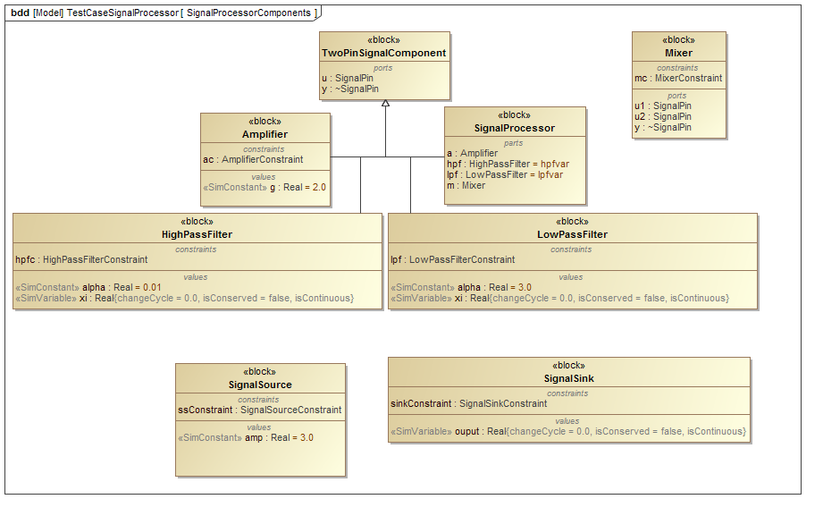
SignalProcessorComponents Block Definition Diagram: This diagram contains a block describing a generic two-pin (ports) signal component class, TwoPinSignalComponent, that is a generalization of other blocks. The generalization contains a block describing the SignalProcessor class and its properties, a block describing the Amplifier class and its properties, a block describing the HighPassFilter class and its properties, and a block describing the LowPassFilter and its properties. The latter three of these blocks as well as the block describing the Mixer class (and its properties) will be shown to be related to the SignalProcessor class in internal body diagrams. There is also a block describing the SignalSource class that generates numeric information for signal flow as well as a block describing the SignalSink class that receives the signal flow.
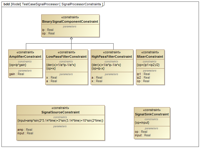
SignalProcessorConstraints Block Definition Diagram: Mathematical expressions are provided in constraint blocks AmplifierConstraint, LowPassFilterConstraint, HighPassFilterConstraint that make use of the parameters used in the constraint block BinarySignalComponentConstraint.These three constraint blocks, along with the MixerConstraint constraint block, describe the filtering and mixing of the generated signal that goes through the signal processor. The SignalSinkConstraint constraint block expresses the output of the signal processor as the output of the entire system, and the SinalSourceConstraint constraint block provides the generated input signal that flows through the system.
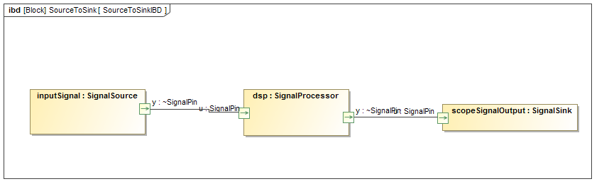
SourceToSinkIBD Internal Block Diagram: This diagram is part of the SourceToSink block. The flow of signal between the part properties inputSignal (typed by SignalSource), dsp (typed by SignalProcessor), and scopeSignalOutput (typed by SignalSink) is shown to be going through pins typed by SignalPin. These pins are the interface between the three connected system components.
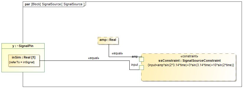
SignalSource Parametric Diagram: The constraint parameters (variables in the mathematical expressions of the constraints) of the SignalSourceConstraint constraint block are bound to the properties and ports of the SignalSource block (from the SignalProcessorComponents block definition diagram).
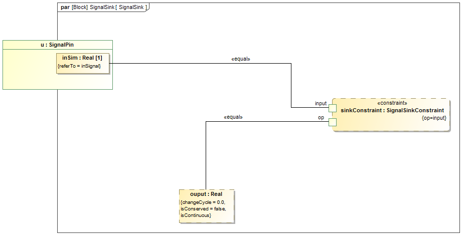
SignalSink Parametric Diagram: The constraint of the SignalSinkConstraint constraint block are bound to the properties and ports of the SignalSink block (from the SignalProcessorComponents block definition diagram).
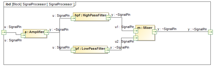
SignalProcessor Internal Block Diagram: This diagram is part of the SignalProcessor block and shows how the signal becomes amplified, filtered, and then remixed again. The flow of signal between the part properties hpf (typed by HighPassFilter), lpf (typed by LowPassFiler), a (typed by Amplifier), and m (typed by Mixer) is shown to be going through ports typed by SignalPin. These ports serve as interfaces where the signal flows from one part to the other.
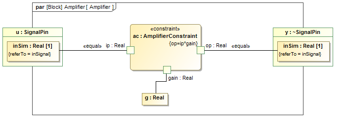
Amplifier Parametric Diagram: The constraints of the AmplifierConstraint constraint block are bound to the properties and ports of the Amplifier block (from the SignalProcessorComponents block definition diagram).
LowPassFilter Parametric Diagram: The constraint of the LowPassFilterConstraint constraint block are bound to the properties and ports of the LowPassFilter block (from the SignalProcessorComponents block definition diagram).

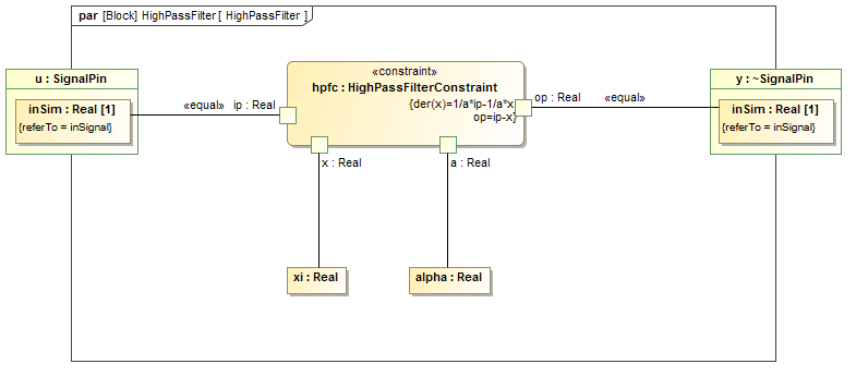
HighPassFilter Parametric Diagram: The constraint of the HighPassFilterConstraint constraint block are bound to the properties and ports of the HighPassFilter block (from the SignalProcessorComponents block definition diagram).
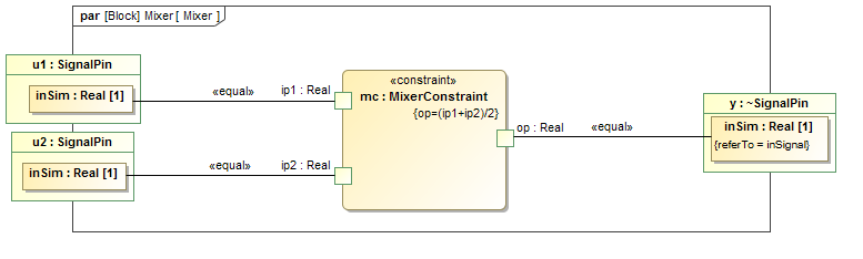
Mixer Parametric Diagram: The constraint of the MixerConstraint constraint block are bound to the properties and ports of the Mixer block (from the SignalProcessorComponents block definition diagram).