To generate a Simulink model directly from the modeling tool
- Right-click the Block TestCaseCircuit::Circuit and select Tools > Export to Simulink. Please see Generating a simulation file for more information.
- Set the options listed below and click OK:
- Format: XML (.sdl)
- S-Function or Simscape: Simscape
- Simscape port libraries: Create new port types
- Launch Matlab with Simulink and Simscape extensions.
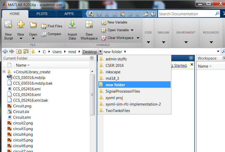
- In Matlab’s Current Directory navigation bar, search for the file directory where the Simulink/Simscape files (as well as the SysML files) are saved, and set it as the current directory. The Current Folder panel should display the generated files.
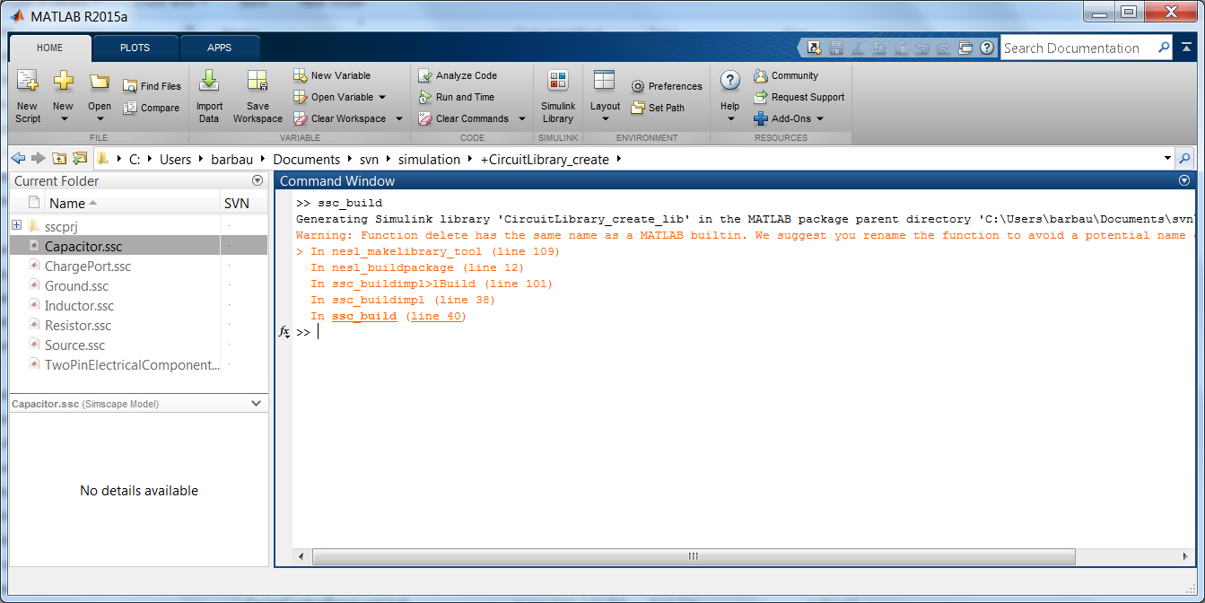
- In the Current Folder panel, double-click on the folder named +CircuitLibrary_create (this sets the current directory to this folder). Type ssc_build (or sscbuild depending on the Matlab version) in the Command Window and press Enter. This will generate a folder sscprj in the +CircuitLibrary_create directory as well as a CircuitLibrary_create_lib.slx file in the directory with the original Circuit.slx file. Next, once again, search for and go back to the file directory where the Simulink/Simscape files (as well as the SysML files) are saved, and then set it as the current directory.
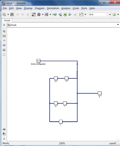
- In the Current Folder panel, double-click on Circuit.slx to open the Simulink/Simscape model. Rearrange the blocks to get a better picture of the blocks and links.
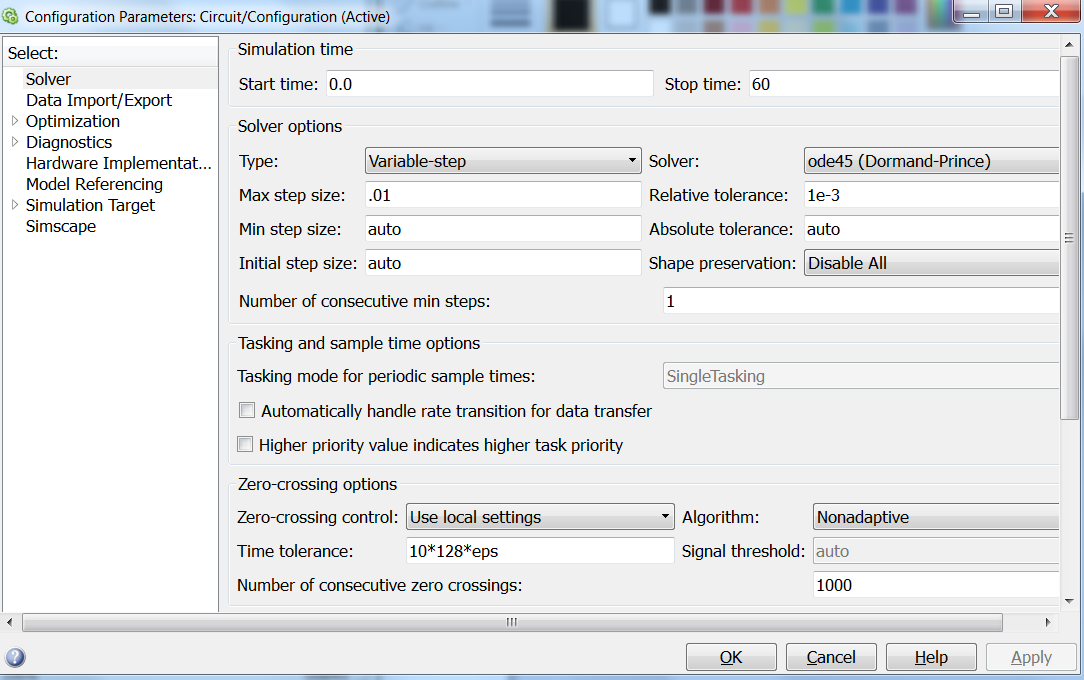
- Go to Simulation > Model Configuration Settings. This allows to select the types of solver and the runtime of the simulation. Select a Start Time of 0, and a Stop Time of 60 (or any other reasonable number of seconds). Change the Max step size to 0.01. Under Solver Options, keep the solver Type to Variable-step (or any other desirable solver that is suitable). Press Apply.
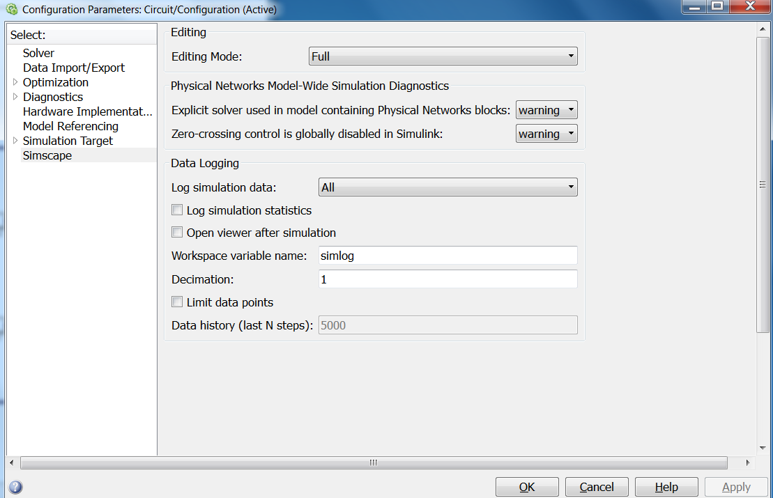
- In Model Configuration Settings, select Simscape in the Commonly Used Parameters panel. Change Log simulation data to All. Make sure Limit data points is unchecked. Press Apply. Press OK.
- In the Circuit Simulink window, go to Simulation > Run.
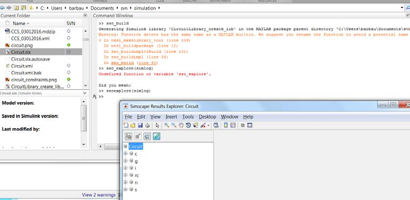
- Once the model has compiled, go to Matlab’s command window and type/enter ssc_explore(simlog) (make sure that either the version of Matlab has the function ssc_explore, or a file ssc_explore.m is in the same directory as Circuit.slx in the Current Folder panel). A Simscape data logging explorer: Circuit window will open up.
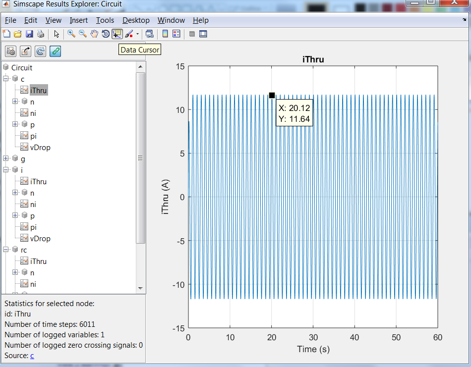
In the Simscape data logging explorer, the Circuit blocks can be expanded to see how their properties simulated through time. For the circuit components c (capacitor), i (inductor), rc (resistor in series with the capacitor), ri (resistor in series with the inductor), and s (source), the properties iThru (current) and vDrop (voltage) can be selected to see the flow of charge (current) and its potential to flow (voltage) through each component. To see the simulation’s specific data points, the Data cursor icon needs to be selected and points on the plot need to be chosen.
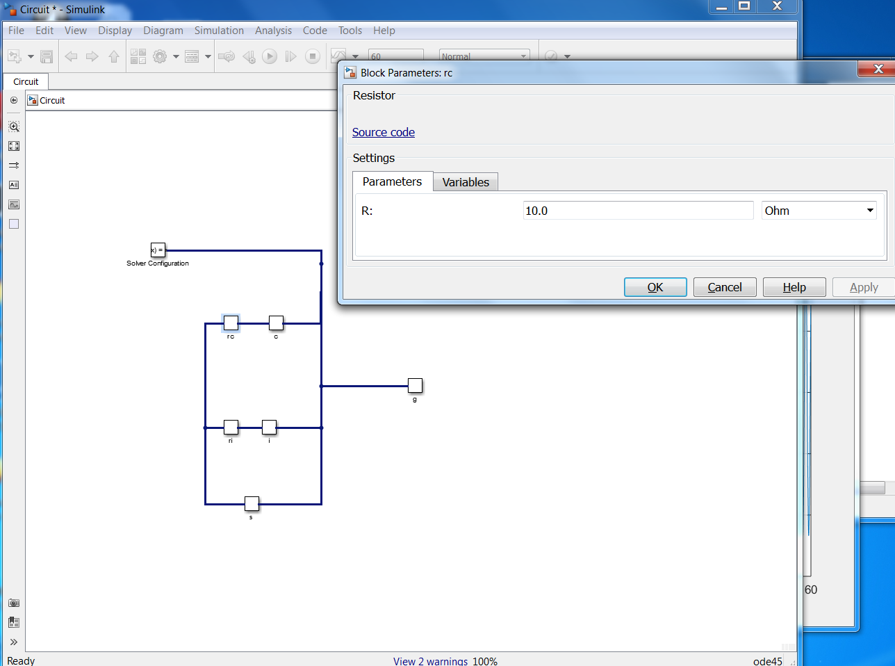
- To change the default value or initial value parameters of the model, double-click the blocks in the Circuit Simulink model. A window will pop out for block parameters that can be changed. Run through Steps 4 through 8 to run the simulation with (new) block parameters again.