On this page
Introduction
When describing your system structure, you should start from defining Blocks in SysML Block Definition Diagram. Blocks represent the system hierarchy in terms of systems and subsystems. You can model either the logical or physical decomposition of a system, and the specification of software, hardware, or human elements.
The notation for a Block is a rectangle with the stereotype «block» preceding the name. Blocks are the elements of definition because they have a name only. The figure below, illustrates the vehicle structure of defined Blocks in the SysML Block Definition Diagram. The figure is created from VehicleStructure.mdzip sample model.
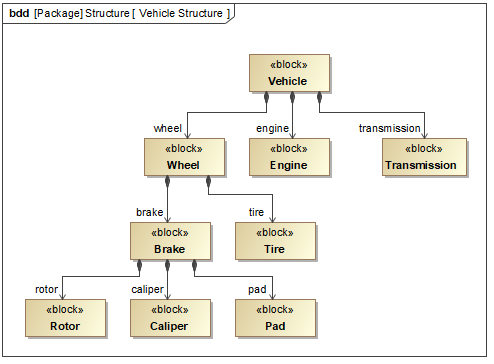
The vehicle structure in SysML Block Definition Diagram.
Creating Blocks
You can create Blocks in SysML Block Definition Diagram in the following ways:
Use Create Element dialog in the Model Browser
You can create all elements including Blocks in the Model Browser from the shortcut menu.
To create Block in the Model Browser
- In the Model Browser, right-click the Package in which you want to store the new Block.
- Do one of the following:
- From the shortcut menu, select Create Element.
- Press Ctrl+Shift+E. - In the Create Element dialog, select Block.
- Type its name.
The new Block is created in the Model Browser. You can represent it in the SysML Block Definition Diagram by dragging it from the Model Browser onto diagram pane.
Use the palette on the diagram pane
You can create Blocks directly on the SysML Block Definition Diagram pane. The Blocks created on diagram pane are created in the Model Browser too.
To create Block on the diagram pane
- Open the existing SysML Block Definition Diagram or create new. How to create a new diagram >>
- Do one of the following:
- From the diagram palette, select the Block button.
- Press B. - Click on the diagram pane.
- Type its name.
The new Block is created in the Model Browser and represented in the SysML Block Definition Diagram.
Paste list in the Containment tree or on diagram pane
You can create Blocks by copying a listed text from other resources (e.g. Word, Excel, HTML, etc.) and pasting it either in the Containment tree or diagram pane.
The detailed procedures are provided in the Creating elements from other resources page.
Drag .fmu file on the diagram pane
You can represent any model components that are exported to Functional Mock-up Interface (FMI) standard (.fmu files) as Blocks in the SysML Block Definition Diagrams.
SysML Plugin supports FMI 1.0 and 2.0 versions.
To represent .fmu file as the Block
- Drag .fmu file on the Block Definition Diagram pane.
The Block with name, value properties, their types, and applied fmu stereotype is created.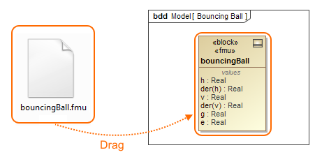
You can execute one fmu Block or co-simulate cooperated fmu Blocks using Cameo Simulation Toolkit.
Creating Association Block
You can use an Association Block to show decomposition of the connector in a similar way that blocks show the decomposition of parts. You can create an Association Block or Association Block with Owned Ends between two Blocks in the SysML Block Definition Diagram. You can represent Association Block usages in the SysML Internal Block Diagrams by setting Association Block as Connector type.
To create an Association Block or Association Block with Owned Ends
- Create two Blocks on diagram pane.
- From the diagram palette, select Association Block or Association Block with Owned Ends button.
- On the diagram pane, select a Block to be used as the source.
- Select a target by either selecting an existing Block on the diagram pane, or by clicking on empty space on the diagram to create the target Block.
An Association Block or Association Block with Owned Ends is created between the source and target Blocks. The Participant Properties are created for the Association Block automatically and shown in it's references compartment area.
Participant properties are created automatically after an Association Block is created between Blocks.
The following figure shows two Association Blocks: Water Delivery and Plumbing. The connection between Spigot Bank Block and Faucet Blocks is decomposed into Water Delivery Block by creating an Association Block. The suppliedByInLink and deliveredToInLink Participant Properties are created and shown in the compartment area. The same is with Plumbling Association Block. The figure is created from WaterSupply_19.0.mdzip sample model.
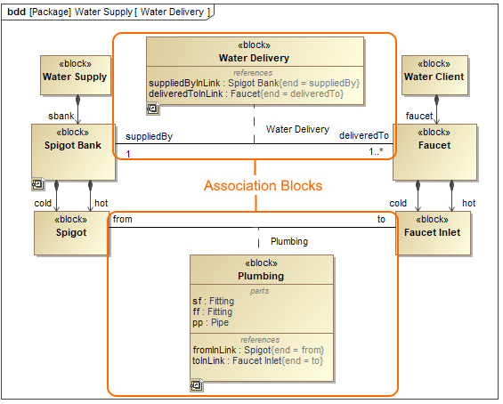 Water Delivery and Plumbing Association Blocks in the SysML Block Definition Diagram.
Relating Blocks
You can connect Blocks by using the main relationships as follows:
Generalization
The Generalization relationship conveys an inheritance between Blocks. It is usually used to create a hierarchy in your system. The notation is a solid line with a hollow, triangular arrowhead on the end.
The figure below shows that the DC Power Supply, Inverted Pendulum System, and Computer Blocks are types of AC Device Block. It means that all of the subtypes (DC Power Supply, Inverted Pendulum System, and Computer) require all the characteristics of AC Device but add their own specialized characteristics as well. The figure is created from InvertedPendulum.mdzip sample model. 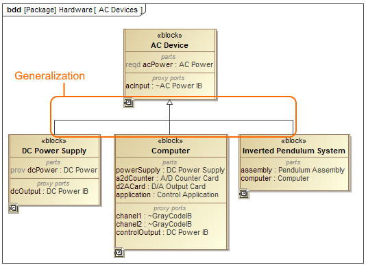
Generalization relationship between Blocks in SysML Block Definition Diagram.
Direct Composition or Composition
The Direct Composition or Composition relationships convey a structural decomposition of Blocks. The notation is a solid line between two Blocks with a solid diamond on the composite end.
The following figure shows that the Wheel is composed of Tire and Brake. The Composition can be represented in two different ways: by showing Composition relations between Blocks or by showing Part Properties on decomposed Block compartment. The figure is created from the VehicleStructure.mdzip sample model.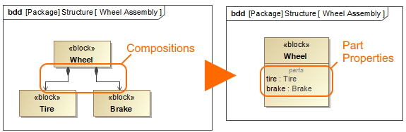
Direct Composition relationship between Blocks in SysML Block Definition Diagram.
Direct Association or Association
The Direct Association or Association convey that a connection can exist between those Blocks. Those Blocks can access each other for some purpose across the connection. The Direct Association notation is a solid line with an arrowhead on the end, while Association notation - only solid line.
The figure below illustrates the Associaton between Wheel and WirelessTirePressureMonitor Blocks. The name of the Association is BandMount which describes the type of connection that could exist between the wheel and wireless tire pressure monitor. Association can be represented in two different ways: by showing Association relation between Blocks or by showing Reference Property on decomposed Block compartment. The figure is created from the hybrid sport utility vehicle.mdzip sample model.
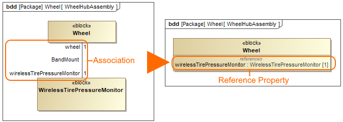
Association relationship between Blocks in SysML Block Definition Diagram.
How to create, remove, change a style, route, create a line jump, insert a shape on a path, or manage path compartments, read in the Working with paths and relationships page.