In this model an electric circuit is built using a source, a ground, two resistors, a capacitor, an inductor, as well as ports that allow to connect these circuit components to show the flow (and potential to flow) of charge from one component to the other. In total, there are 8 SysML diagrams in this model:
- CircuitComponents Block Definition Diagram: This diagram contains a block describing a generic two-pin (ports) electrical component class, TwoPinElectricalComponent, that serves as a generalization of other blocks. The generalization contains a block describing the Resistor class and its properties, a block describing the Inductor class and its properties, a block describing the Capacitor class and its properties, and a block describing the Source class and its properties. There is also a block describing the Ground class that is needed as a reference point for the flow potential (voltage) of charged particles in an electric circuit.

- CircuitConstraints Block Definition Diagram: Mathematical expressions are provided in constraint blocks ResistorConstraint, CapacitorConstraint, InductorConstraint, and SourceConstraint that extend the mathematical constraints and parameters defined in BinaryElectricalComponentConstraint for each of their respective constraint block classes. These four constraint blocks, along with the mathematical expressions in the GroundConstraint constraint block, describe the flow and potential to flow behavior of charged electric particles that go through different components in the electric circuit.

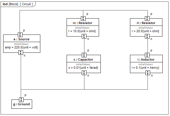
- Circuit Internal Block Diagram: This diagram is part of the Circuit block, and it shows layout of components in the electric circuit design. The links between the ports of the components depict the physical interactions that occur in the electric domain, that is the flow (current) and potential to flow (voltage) of the charged particles that move through the electric circuit.
- Capacitor Parametric Diagram: The constraint parameters (variables in the mathematical expressions of the constraints) of the CapacitorConstraint constraint block are bound to the properties and ports of the Capacitor block (from the CircuitComponents block definition diagram).

- Ground Parametric Diagram: The constraint parameters (variables in the mathematical expressions of the constraints) of the GroundConstraint constraint block are bound to the potential to flow property of the Ground block’s port (from the CircuitComponents block definition diagram).

- Inductor Parametric Diagram: The constraint parameters (variables in the mathematical expressions of the constraints) of the InductorConstraint constraint block are bound to the properties and ports of the Inductor block (from the CircuitComponents block definition diagram).

- Resistor Parametric Diagram: The constraint parameters (variables in the mathematical expressions of the constraints) of the ResistorConstraint constraint block are bound to the properties and ports of the Resistor block (from the CircuitComponents block definition diagram).

Source Parametric Diagram: The constraint parameters (variables in the mathematical expressions of the constraints) of the SourceConstraint constraint block are bound to the properties and ports of the Source block (from the CircuitComponents block definition diagram).
