This page describes how to simulate ElectricCircuit example model in Simulink. Learn more about ElectricCircuit sample model >>
You can find the ElectricCircuit sample model in:
- the modeling tool: Welcome window > Samples > Simulink and Modelica Transformation > ElectricCircuit.
- the Installation directory: <modeling tool installation directory>\samples\SysML\Simulink and Modelica Transformation\ElectricCircuit.
To simulate the Electrical Circuit model
- Export the Circuit Block to Simulink file. How to >>
- In the Simulink Export Options dialog select the following options:
Format: XML (.slx)
S-Function or Simscape: Simscape
- Simscape port libraries: Create new port types
- Composite Signals: Bus Creators/Selectors
- Make sure the MATLAB tool is installed.
- Double-click the MATLAB icon to start it.
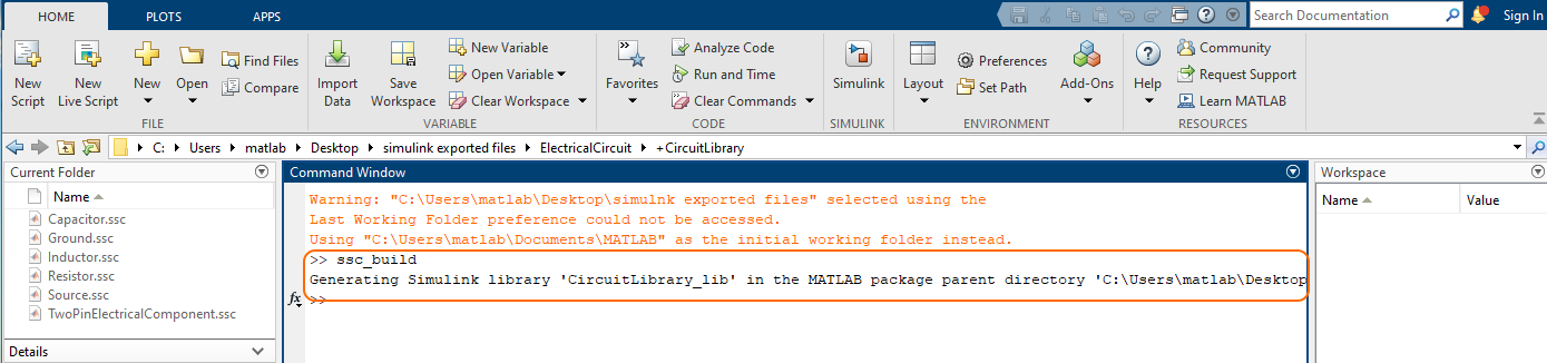
- In the file directory select the location of your exported ElectricalCircuit model Simulink files and choose the +CircuitLibrary folder. The simscape files (.ssc) are displayed in the Current Folder panel.
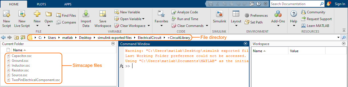
- In the Command Window type ssc_build (or sscbuild depending on the Matlab version) and press Enter. This generates a folder sscprj in the +CircuitLibrary directory as well as a CircuitLibrary_lib.slx file in the directory with the original Circuit.slx file.
- Go back to the file directory, select the ElectricalCircuit package with exported Simulink files and in the Current Folder select the Circuit.slx.
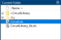
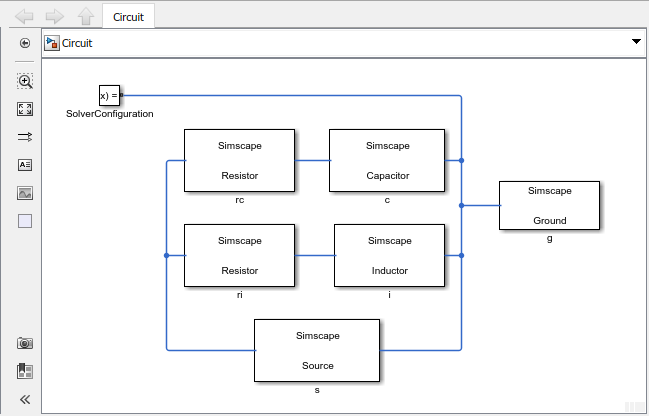
- Double-click on Circuit.slx to open the Simulink/Simscape model. Rearrange the blocks to get a better picture of the blocks and links.
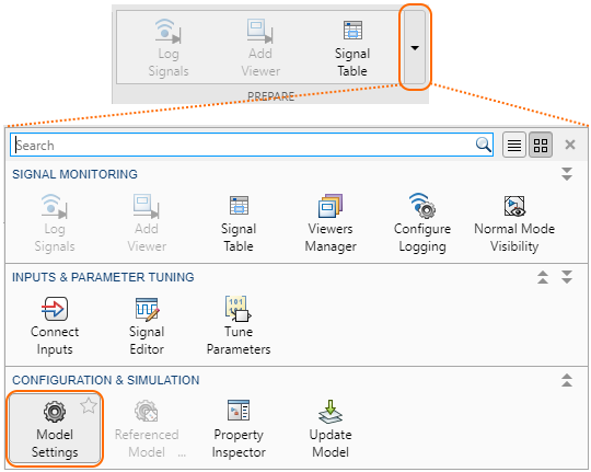
- On the SIMULATION tab, click the arrow on the PREPARE area and select the Model Settings.
- In the Configuration Parameters dialog, on the left side of the dialog:
a. Select a Solver property group and specify the following on the right side of the dialog:
- In the the Simulation time group, change Start time to 0.0, Stop time to 60 (or any other reasonable number of seconds).
- In the Solver selection group, select Type Variable-step or any other desirable solver that is suitable.
- Click the arrow of the Solver details group and change the Max step size to 0.01.
b. Select Simscape property group and specify the following on the right side of the dialog:
- In the Data Logging group, change Log simulation data to All.
- Make sure Limit data points is unchecked.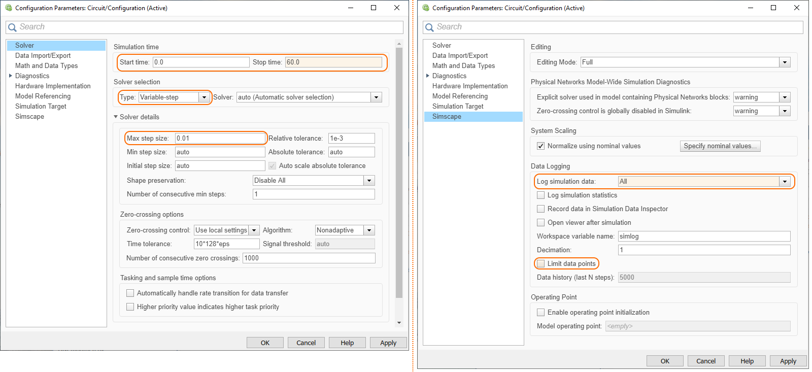
- Press Apply > OK.
- In the Circuit Simulink window, click
 .
. - Once the model has compiled, on the main toolbar, click
 to open a Simscape Results Explorer: Circuit window where you can expand the Circuit blocks to see how their properties simulated through time. For the circuit components c (capacitor), i (inductor), rc (resistor in series with the capacitor), ri (resistor in series with the inductor), and s (source), the properties iThru (current) and vDrop (voltage) can be selected to see the flow of charge (current) and its potential to flow (voltage) through each component. To see the simulation’s specific data points, select the mouse pointer on the plot.
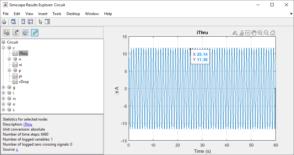
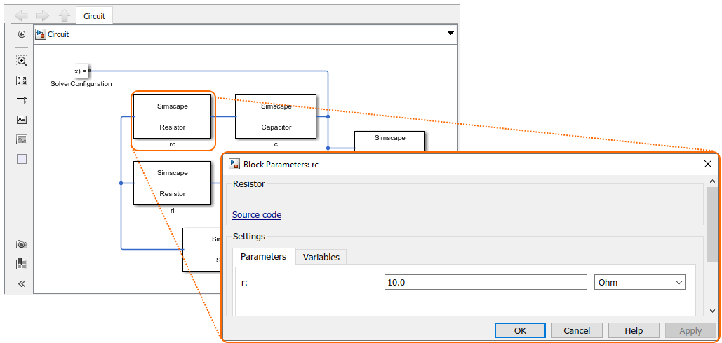
- To change the default value or initial value parameters of the model, double-click the blocks in the Circuit Simulink model. A Block Parameters dialog opens where yoy can change parameters. Repeat steps from 5 to 12 to run the simulation with (new) block parameters.