The purpose of a Use Case Diagram is to give a graphical overview of the functionalities provided by a system in terms of actors, their goals (represented as use cases), and any dependencies among those use cases.
A Use Case Diagram describes the usage of a system. The associations between actors and use cases represent the communications that occur between the actors and the subjects to accomplish the functionalities associated with the use cases. The subject of a use case can be represented through a system boundary. The use cases enclosed in the system boundary represent the functionalities performed by behaviors (activity diagrams, sequence diagrams, and state machine diagrams).
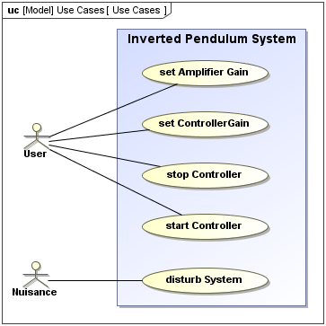
Actors may interact either directly or indirectly with the system. They are often specialized so as to represent a taxonomy of user types or external systems. The only relationship allowed between actors in a use case diagram is generalization. This is useful in defining overlapping roles between actors. Actors are connected to use cases through communication paths, each represented by a relationship. There are four use case relationships:
Communication
A communication path represents an association between two Deployment Targets. It connects actors to use cases.
Include
An include relationship provides a mechanism for factoring out a common functionality that is shared among multiple use cases and is always performed as part of the base use case.
Extend
An extend relationship provides an optional functionality, which extends the base use case at defined extension points under specified conditions.
Generalization
A generalization relationship provides a mechanism to specify variants of the base use case.
Use cases are often organized into packages with the corresponding dependencies among the use cases included in the packages.