Implementation
OV-2 can be represented using:
- An OV-2 diagram which is based on the UML Class diagram.
- An OV-2 diagram which is based on the UML Composite Structure diagram.
- A UML Class diagram.
- A UML Composite Structure diagram.
- A SysML Block Definition diagram.
- A SysML Internal Block diagram.
Sample
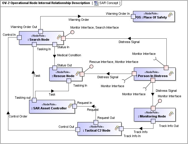
OV-2 Operational Node Internal Relationship Description
Related views
An OV-2 is highly related with an OV-5. Operational Nodes shown in the OV-2 are the performers of the Operational Activities modeled in the OV-5. OV-2 focuses on the Operational Nodes, with the activities being a secondary adornment. The OV-5, on the other hand, places first-order attention on operational activities and only second-order attention on Nodes, which can be shown as annotations or swim-lanes on the activities.
Information flows can be modeled either in the OV-2 or OV-5. In both cases they are highly associated and in general should be reused between these views.
The OV-2 displays the Capabilities required by Nodes from StV-2. That is an association between two abstraction levels of user requirements where the OV is more specific than the StV and a Node is more specific concept than a Capability.
The other important mapping is between OV-2 and SV-1. The specification Node and implementation Resource are subjects to map here. One OV-2 product can have several implementations in the SV-1.
- Known Resource
- Needline
- Node Port
- Node Role
- Operational Exchange
- Service Channel
- Service
- Property
- Request
- Creating OV-2 diagram
- Creating Operational Exchanges in OV-2 diagram