In the Containment Tree, select the Operational Connectivity and do one of the following:
From the selected package's shortcut menu, select Create Diagram > Operational Connectivity.
In the modeling tool's main menu, click Create Diagram, search for Operational Connectivity and select it.
Name a diagram or leave it with the default name.
Creating an element
When the diagram is created, you can start creating the appropriate elements. An example is described using Operational Performer element, but the same is valid for other structural elements.
To create an Operational Performer in a diagram
In the diagram palette, click the Operational Performer and then click the appropriate place on the diagram pane.
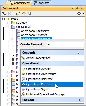
To create an Operational Performer in a Containment tree
In the Containment tree, right click the Operational Structure package and from the shortcut menu, select Create Element. Search for the Operational Performer and select it.
Name the element.
Drag the created element from the Containment tree to the diagram pane.
An Operational Connectivity view also allows you to show mappings among Capabilities and Operational Performers, Physical Location requirements, and Services provided or requested by Operational Performers.
Before creating Operational Exchanges, one or more exchange items should be created (e.g. Information Element, Data Element, or Resource). The you can start creating Operational Exchanges.
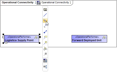
To create an Operational Exchange in the Operational Connectivity diagram
Do one of the following:
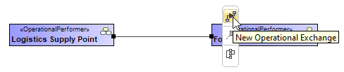
On the diagram pane, select an Operational Performer and in the smart manipulator toolbar, click Operational Exchange. Click another Operational Performer to connect.
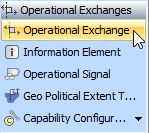
In the diagram palette, click Operational Exchange and on the diagram pane, connect Operational Performers.
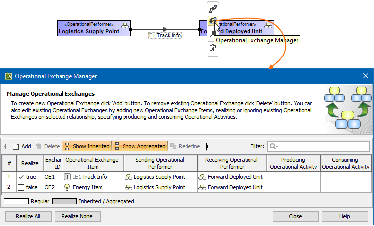
Once an Association Relationship is created between two structural elements, all existing exchanges between the elements are visible in the Operational Exchange Manager dialog.
To open an Operational Exchange Manager dialog
Select an Association (also Operational Connector, Operational Control Flow, Operational Object Flow, or Operational Message) in the diagram pane.
In the smart manipulator, click . The Operational Exchange Manager dialog opens.
Click to select or clear the check box in the Realize column to show (realize) or hide Operational Exchanges on the Association.
Dragging the Exchange Item on the Association
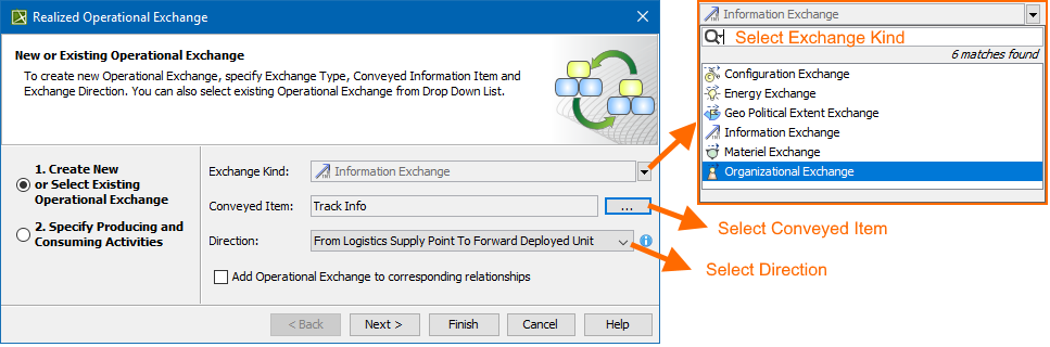
You can create the Operational Exchanges on the Association by dragging the Exchange Elements onto the Association. When you drop the Exchange Element on the Association, the Realized Operational Exchange wizard opens.
In the wizard, specify the needed information.
In the Operational Exchange drop-down list, the existing Operational Exchanges will be listed.