Boundary Diagram
Basic Concepts
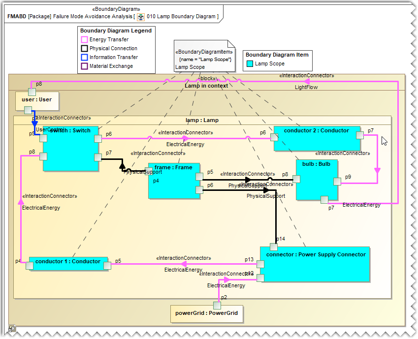
Boundary diagram and Boundary diagram item aid in identifying and capturing in exhaustive detail about :
- The Internal sub-systems and components, and external “actors”/entities
- The different scopes of analysis by visually outlining the system boundary.
- The interactions with legends
- Missing interactions.
Creating a Boundary Diagram
To create a Boundary Diagram
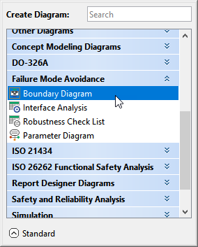
- In the Containment tree, right-click the Boundary Diagram package and select Create Diagram.
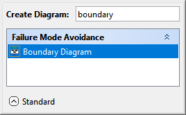
- Do one of the following:
- In the dialog, expand Failure Mode Avoidance and select Boundary Diagram.
- In the search tab, type the keyword boundary and then select Boundary Diagram.
- In the dialog, expand Failure Mode Avoidance and select Boundary Diagram.
The Boundary Diagram is now displayed in the diagram pane and in the Containment tree of the modeling tool.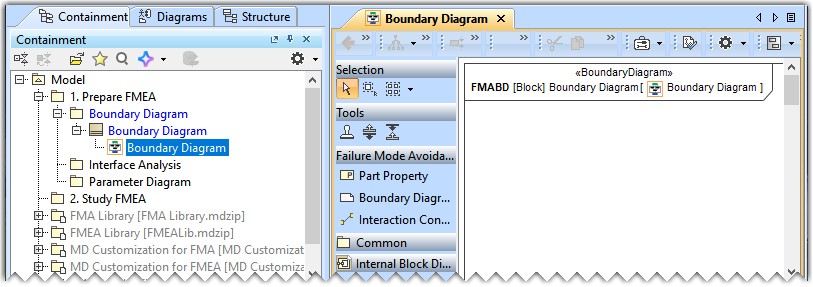
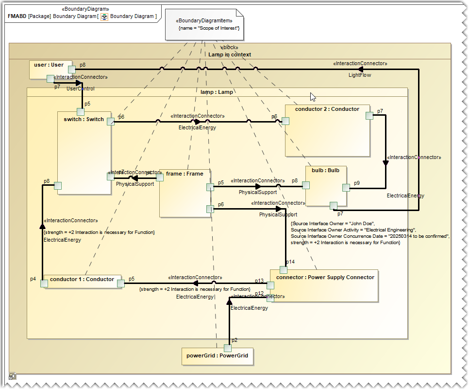
Adding an Internal Block Diagram of a Use Project
To add an Internal Block Diagram of a Use Project
- Add the required local project to your project. To learn more, refer to the Using local projects page.
- Drag and drop the required block from the Containment tree to the Boundary Diagram.
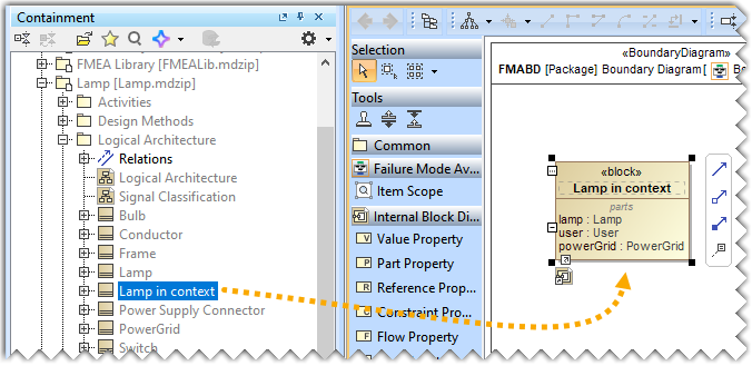
- Right-click the block and select Display>Display Internal Structure>Lamp in context>Lamp in context.
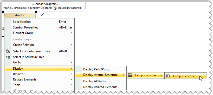
The internal structure of the Lamp block is displayed in the diagram pane.
Creating a Boundary Diagram Item
To create a Boundary Diagram Item
- Drag and drop the Boundary Diagram Item element in the diagram pane.
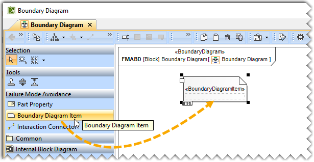
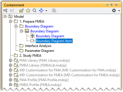
- In the Containment tree, select the newly created Boundary Diagram Item and rename it with the help of the Specification dialog.
Drawing an Anchor
To draw an Anchor
- Draw an anchor from the newly created Item Scope to the elements of interest. To learn more about drawing and configuring an Anchor, refer to the Anchor page.
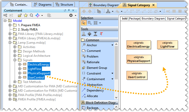
Creating a Signal Category
To create a Signal Category
- Create a SysML Block Definition Diagram in the Boundary Diagram package. To learn more about creating a diagram, click here.
- Drag and drop the signals from the Lamp>Signals package in the diagram pane.
- Drag and drop the EnergyTransfer, InformationTransfer, InteractionClass, MaterialExchange, and PhysicalConnection elements from the FMA Library package in the diagram pane.
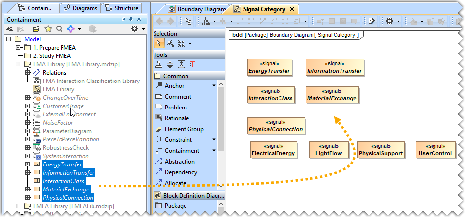
- Rearrange the elements and create Dependencies as per your requirements. To learn more about creating Dependency, refer to the Dependency page.
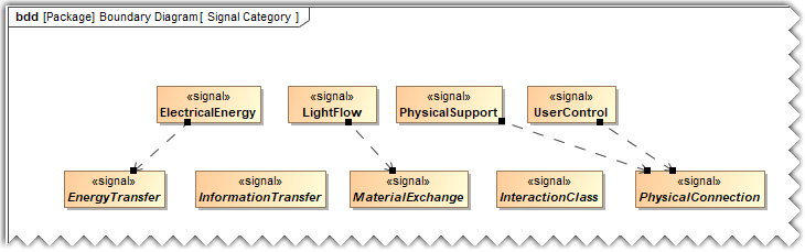
- Select and apply the TransferType[Dependency] stereotype to all the dependencies. To learn more about applying stereotype, refer to the Stereotype page.
- On the diagram toolbar, click the
 button to change the diagram layout. To learn more about changing diagram layout, refer to the Layout page.
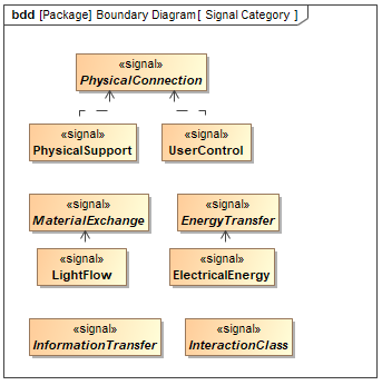
Working with Legends
A Legend is a model element that allows you to define the styles of diagram symbols and table rows. It helps you to visually group model elements according to specified criteria. A Legend increases the readability of the diagram and table contents by highlighting important information. To learn more, refer to the Legends page.
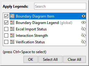
Applying a Legend
To apply a Legend
- In the diagram toolbar. Click
 and from the drop-down menu, select Apply Legends.
 - Select the Legend(s) you want to display and click OK.
To learn more, refer to the Applying Legends page.
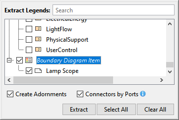
Extracting a Legend
To extract a Legend
- In the diagram toolbar. Click and from the drop-down menu, select Extract Legends.
- Select the Legend(s) you want to display and click Extract.
To learn more, refer to the Extracting Legends page.
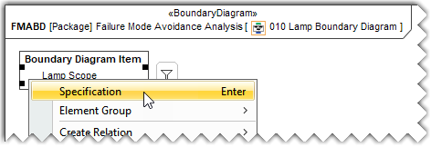
Specifying Legend Item adornment
To open the adornment properties of a Legend Item
Open the Specification window of the Legend Item Lamp Scope in the Boundary Diagram Item.
- Click the specification cell of the Adornment property, and then click
 .
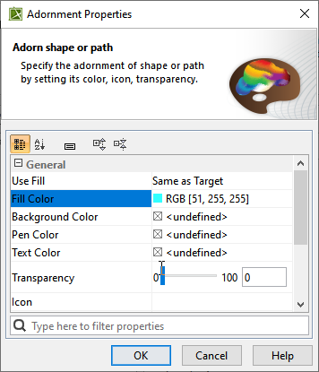
. - In the Adornment Properties dialog, specify the Fill Color property and click OK.
To learn more, refer to the Specifying Legend Item adornment.
After completing the above procedures, the Boundary Diagram is updated in the following manner.