Robustness Checklist
Basic Concepts
For a specific function/activity, a Robustness Check List allows verifying that prevention controls (design methods) and detection controls (test methods) are adequate given the impact of failure modes/failure effects to be covered and the range of variation of noise factors that cause these failure modes/failure effects to arise.
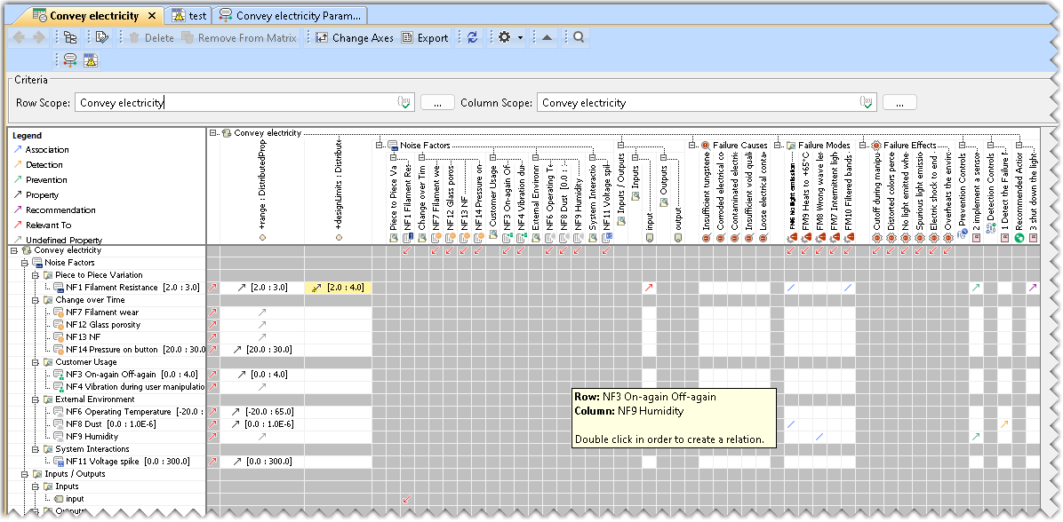
The rows and columns of the Robustness Check List display the noise factors with their associated ranges of variation, the failure causes, the failure modes, the failure effects, the prevention controls, the detection controls, and the recommended actions associated with the function/activity for which the RCL is established. All these elements could come from the function/activity Parameter Diagram, except the failure causes, which are introduced manually in the Robustness Check List.
Essential Information:
- The robustness checklist diagram is created based on an activity object.
- All relationships in the Robustness Checklist can be deleted by right-clicking the cell and selecting the corresponding delete command. It can also be deleted from the model itself by pressing the Delete key on the Keyboard.
- The Parameter diagram and the FMEA table also show all existing relationships.
- In case a Parameter Diagram and/or an FMEA table exist for the activity, you can navigate from the Robustness Checklist with the help of the commands present in the toolbar. The following table displays the icons and functions of the commands:
Icon Description 
Opens the Function in the Parameter Diagram 
Opens the Function in the RAAML-based FMEA Table
The Robustness Checklist is a Dependency Matrix. To learn more, refer to the Dependency Matrix page.
Creating a Robustness Checklist
To create a Robustness Checklist
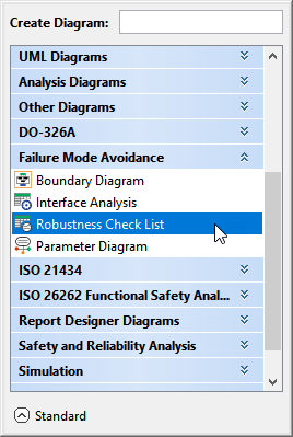
- In the Containment tree, right-click the Robustness Checklist package and select Create Diagram.
- Do one of the following:
- In the dialog, expand Failure Mode Avoidance and select Robustness Checklist.
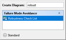
- In the search tab, type the keyword robust and then select Robustness Checklist.
- In the dialog, expand Failure Mode Avoidance and select Robustness Checklist.
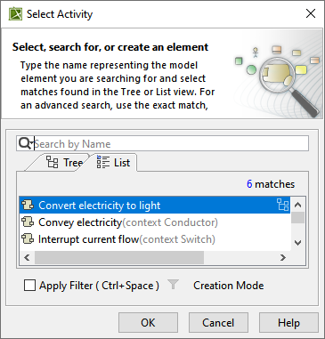
- In the Select Activity dialog, select the required Activity and click OK.
The Robustness Checklist is now displayed in the diagram pane of the modeling tool.
You must focus on identifying relationships with the aid of the white cells, as the grey cells are not editable.
Adding an element to the Robustness Checklist
To add an element to the Robustness Checklist
- In the containment Tree, select the element to be added.
- Drag and drop the element on the Column corresponding to the element folder and refresh the diagram.
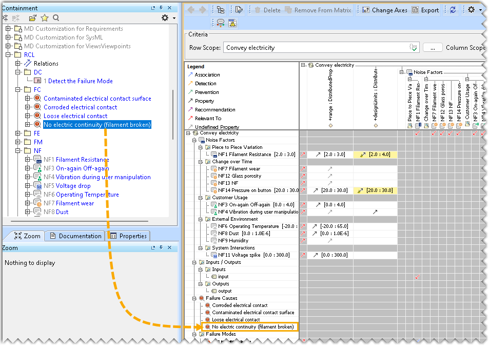
Deleting elements from the Robustness Checklist
To delete elements from the Robustness Checklist
- In the Robustness Checklist, select the element to be deleted.
- Right-click and select Remove from the Matrix from the Contextual menu.
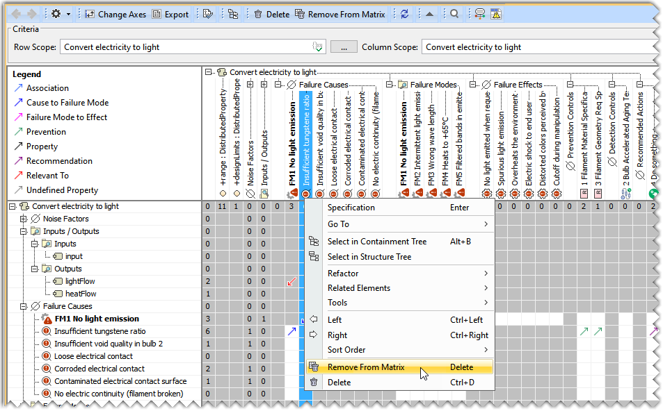
You can completely delete the element by pressing the Delete button on the Keyboard.
Creating a range for the Noise Factor
With the Robustness checklist, you can enter a range describing the boundaries in an existing Unit of measure for the variation of the Noise Factor.
To create a range for the Noise Factor
- Select the cell corresponding to the targeted Noise Factor and the first column Range.
- Right-click and select Define Range from the Contextual menu.
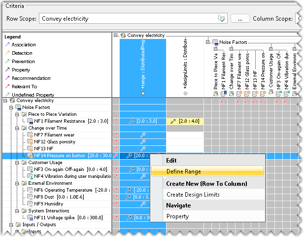
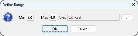
- In the Define Range dialog, insert the required Min value, Max value, and define the Unit.
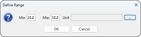
- Click OK.
Creating Design Limits for the Activity
To create a Design Limit for the Activity
- Select the cell corresponding to the targeted Noise Factor and the second column, Design Limits.
- Right-click and select Design Limits from the Contextual menu.
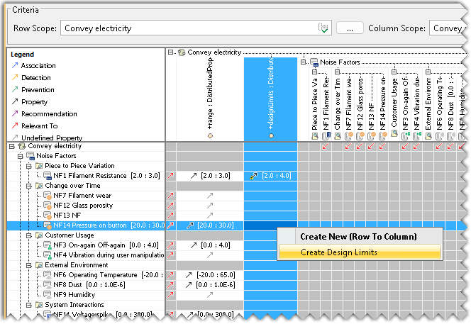
- In the Define Range dialog, insert the required Min value, Max value, and define the Unit.
- Click OK.
Defining coverage for Prevention or Detection Controls
Design methods and test methods may cover a fraction of the range of a noise factor or more than the range of the noise factor. The end user can capture the range of the coverage when a prevention control or detection control is associated to a noise factor using a contextual menu item Define coverage. A dialog allows capturing a minimal value and a maximal value covered by the control, with the same unit as the covered noise factor. The covered range is persisted in the prevention or detection dependency, allowing controls to be enriched without modifying them directly.
The formula to compute the percentage of coverage follows the following rule: if the full range of the noise factor is not covered, the fraction that is covered is computed, and the ratio to the full range of the noise factor is displayed; otherwise, the percentage of coverage is the ratio between the control range and the noise factor range.
To Define Coverage
- Select the cell corresponding to the targeted controls to be defined.
- Right-click and select Define Coverage from the Contextual menu.
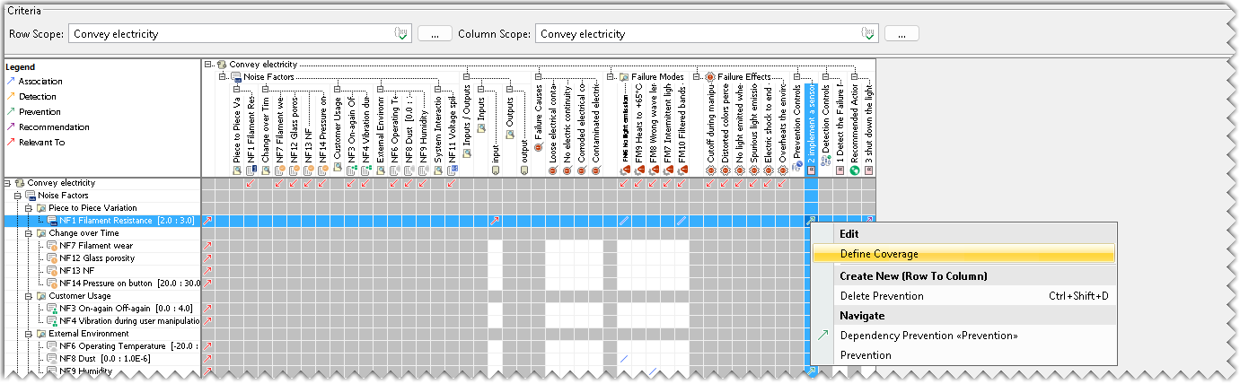
- In the Define Range dialog, insert the required Min value and Max value.
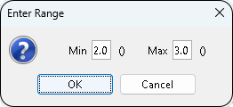
- Click OK.
- The percentage of coverage is displayed in the Robustness Checklist.
The relationship between the control and the other element must be established beforehand.
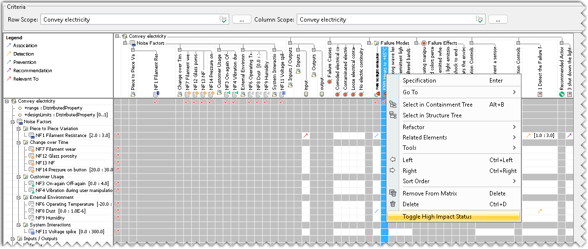
Prioritizing the High Impact Failure Mode
To highlight the High Impact Failure mode in the Robustness Checklist.
- Right-click the required Failure Mode and select Toggle High Impact Status from the Contextual menu.
Creating a Relevant To Relationship
A Relevant To relationship can be created between:
- Noise Factor and Activity Input
- Failure Mode and Activity Output
To create a Relevant To relationship
- Select the white cell between a Noise Factor and an Input.
- Right-click and select Create Relevant To from the Contextual menu.
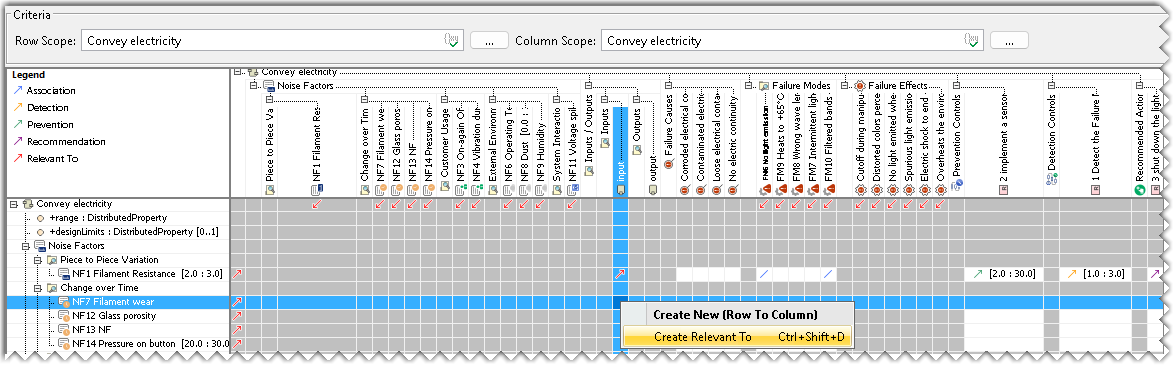
- Select the white cell between a Failure mode and an Output
- Right-click and select Create Relevant To from the Contextual menu.
A dependency is created between the two elements and is visible in the Robustness Checklist with the help of the Red Arrow.
Creating Causality Relationship
A Causality relationship can be created between:
- Noise Factor and Failure Cause
- Noise Factor and Failure Mode
To create a Causality relationship
- Select the white cell between a Noise Factor and a Failure Cause.
- Right-click and select Create Causality from the Contextual menu.
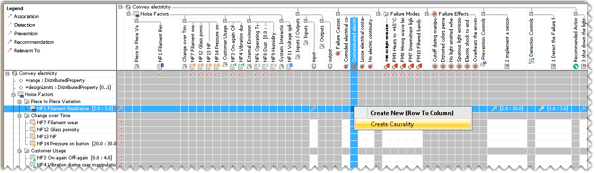
- Select the white cell between a Noise factor and a Failure Mode.
- Right-click and select Create Causality from the Contextual menu.
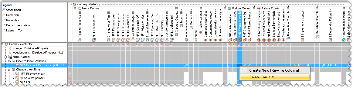
An association is created between the two elements and is visible in the Robustness Checklist with the help of the Blue Line.
Creating a Prevention Relationship
A Prevention relationship can be created between Prevention Control and :
- Noise factor
- Failure Cause
- Failure Mode
- Failure Effect
To create a Prevention relationship
- Select the white cell between the targeted elements.
- Right-click and select Create Prevention from the Contextual menu.
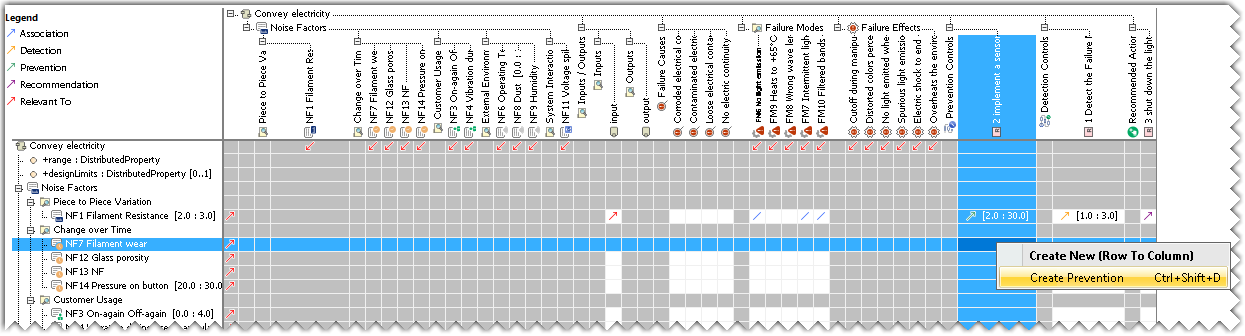
A dependency is created between the two elements and is visible in the Robustness Checklist with the help of the Green Arrow.
Creating a Detection Relationship
A Detection relationship can be created between Detection Control and :
- Noise factor
- Failure Cause
- Failure Mode
- Failure Effect
To create a Detection relationship
- Select the white cell between the targeted elements.
- Right-click and select Create Detection from the Contextual menu.
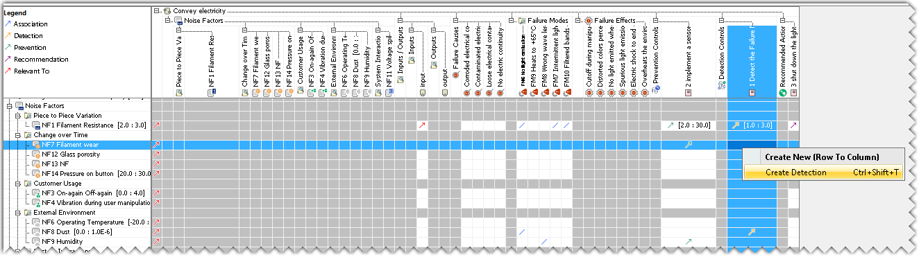
A dependency is created between the two elements and is visible in the Robustness Checklist with the help of the Orange Arrow.
Creating a Recommendation Relationship
A Recommendation relationship can be created between the Recommended Action and :
- Noise factor
- Failure Cause
- Failure Mode
- Failure Effect
To create a Recommendation relationship
- Select the white cell between the targeted elements.
- Right-click and select Create Recommendation from the Contextual menu.
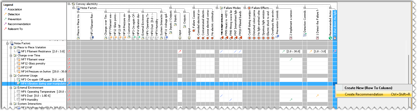
A dependency is created between the two elements and is visible in the Robustness Checklist with the help of the Purple Arrow.
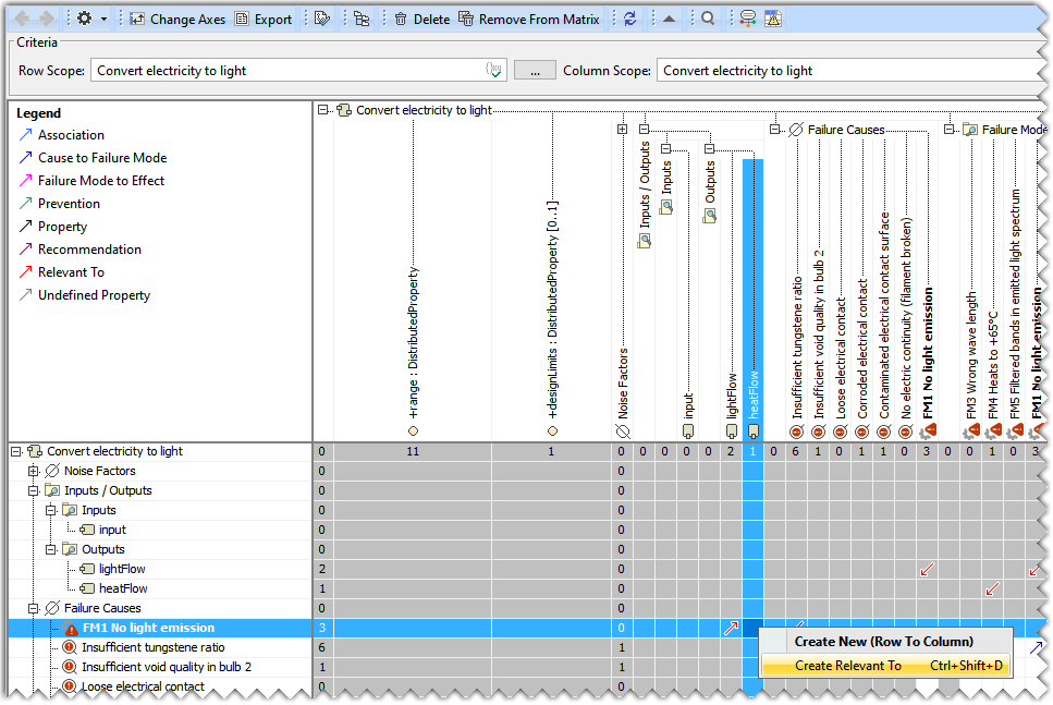
Creating an FMEA Item
An FMEA Item relationship can be created between a Failure Mode and:
- A Failure Cause
- A Failure Effect
To create an FMEA Item
- Select the white cell between the targeted elements.
- Right-click and select Create FMEA Item from the Contextual menu.
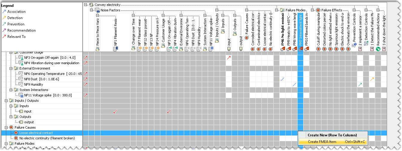
- A Failure Mode to Failure Effect relationship is created between the two elements and is visible in the Robustness Checklist with the help of the Pink Arrow.
- A Failure Cause to Failure Mode relationship is created between the two elements and is visible in the Robustness Checklist with the help of the Dark Blue Arrow.