Parameter Diagram
Basic Concepts
| Concepts | Description |
|---|---|
| Failure Mode | A Failure Mode represents a Specific way in which a component, subsystem, or system can fail to perform its intended function. It describes how the failure happens, i.e., the manner or mechanism of failure, not the cause or the consequence directly, but the mode or form the failure takes. |
| Failure Effect | An element describing the effect that a Failure Mode has on the system element under consideration (user, system, subsystem) |
| Noise Factors | Noise factors are sources of uncontrollable variability in a system. These are typically outside the direct control of the designer and introduce disturbances that may affect performance or reliability. The following are the types of Noise Factors that can be created. |
| Piece-to-Piece Variation Noise Factor | Piece-to-Piece Variation is a noise factor referring to variability between different units or parts of the same product. It can include:
|
| Change Over Time Noise Factor | Change Over Time refers to system or component variations that occur gradually or incrementally during the lifetime of a product, often due to aging, fatigue, wear, drift, or environmental exposure. |
| Customer Usage Noise Factor | A Customer Usage Noise Factor is a type of uncontrollable variation stemming from how different users interact with the product in real-life scenarios, including misuse within plausible limits, erratic behavior, or varying usage environments. |
| System Interaction Noise Factor | A System Interaction Noise Factor is a disturbance or variability introduced by another system, component, or module, which is outside the local design scope, but interacts through a shared interface, environment, or resource.
|
| External Environment Noise Factor | An External Environment Noise Factor is a type of variability introduced by the physical, chemical, or climatic conditions in the system’s operating environment that may affect its behavior, functionality, or lifetime. |
| Control Factor | A Control factor is a design parameter or setting that you can actively choose, design, or adjust to achieve the desired system behavior, despite the presence of noise or variation. |
| Unintended output | An unintended output is any system response, signal, or command that is not expected, not commanded, or not aligned with the intended function, whether due to a failure, error, or disturbance. It should be selected among the type "activity pins" (i.e., object "parameters" and its derivative). |
Creating a Parameter Diagram
To create a Parameter Diagram
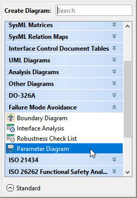
- In the Containment tree, right-click Parameter Diagram package and select Create Diagram.
- Do one of the following:
- In the dialog, expand Failure Mode Avoidance and select Parameter Diagram.
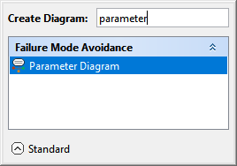
- In the search tab, type the keyword parameter and then select Parameter Diagram.
- In the dialog, expand Failure Mode Avoidance and select Parameter Diagram.
- In the Select Activity dialog, select the required Activity and click OK.
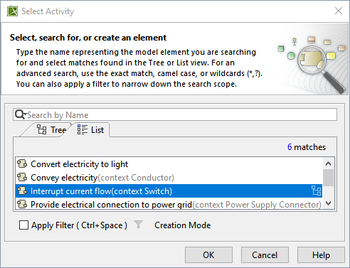
The Parameter Diagram is now displayed in the diagram pane of the modeling tool.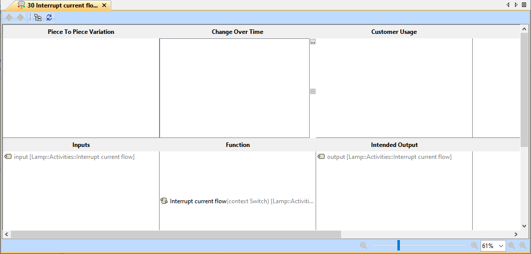
Creating a Failure Mode or Effect
To create a Failure Mode or Effect
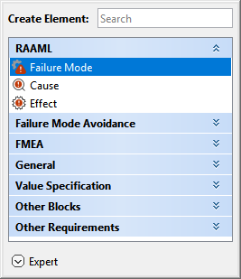
- In the Containment tree, right-click the Parameter Diagram package and select Create Element.
- Do one of the following:
- In the dialog, expand RAAML and select Failure Mode or Effect.
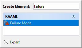
- In the search tab, type the keyword failure or effect, and then select Failure Mode or Effect.
- In the dialog, expand RAAML and select Failure Mode or Effect.
- Name the newly created Failure Mode or Failure Effect in the Containment tree.

An automated number is added with a Counter that is automatically added once validated.
Adding a Failure Mode or Effect in the Parameter Diagram
To add a Failure Mode or Effect in the Parameter Diagram
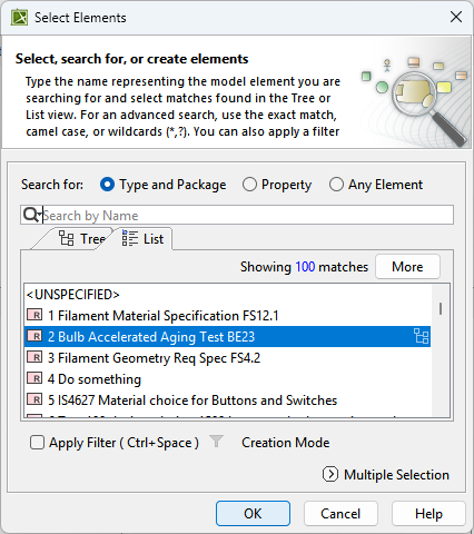
- In the Parameter Diagram, select the Failure Mode or Failure Effect cell and click
 .
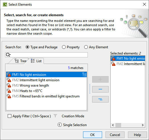
. - In the Select Elements dialog, select the required failure modes or failure effects and click OK. To learn more about selecting elements, refer to the Selecting Elements page.
Creating a Noise Factor
To create a Noise Factor from the containment tree
- In the Containment tree, right-click the Parameter Diagram package and select Create Element.
- Do one of the following:
- In the dialog, expand Failure Mode Avoidance and select the required type of Noise Factor.
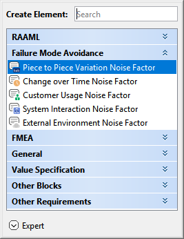
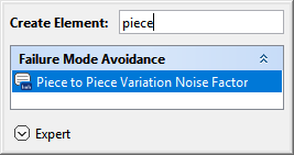
- In the search tab, type the required keyword and then select the required type of Noise Factor.

Optional: You can also enter a range describing the boundaries in an existing Unit of measure for the Variation, or else cancel the range definition.
- In the dialog, expand Failure Mode Avoidance and select the required type of Noise Factor.
- Name the newly created Piece-to-Piece Variation Noise Factor in the Containment tree.
Adding a Noise Factor
To add a Noise Factor in the Parameter Diagram
- In the Parameter Diagram, select the corresponding Noise Factor cell (i.e., Piece to Piece Variation, Change Over Time, Customer Usage, System Interaction, or External Environment), and click .
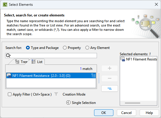
- In the Select Elements dialog, select the required Noise Factor and click OK. To learn more about selecting elements, refer to the Selecting Elements page.
- You can create any type of Noise Factor in the Select Elements dialog. To learn more, refer to the Creating new elements page.
- Optional: You can also enter a range describing the boundaries in an existing Unit of measure for the Variation, or else cancel the range definition.
Creating Control Factor or Unintended Output
To create a Control Factor or Unintended Output from the containment tree
- In the Containment tree, right-click the Parameter Diagram package and select Create Element.
- Do one of the following:
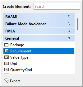
- In the dialog, expand General and select Requirement.
- In the search tab, type the keyword "requirement" and then select Requirement.
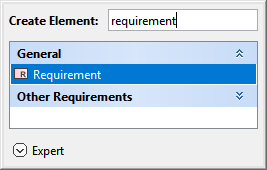
- In the dialog, expand General and select Requirement.
- Name the newly created Requirement in the Containment tree.
An automated number is added with a Counter that is automatically added once validated.
Adding a Control Factor, Unintended Output, or Failure Mode of Unintended Output
To add a Control Factor or Unintended Output in the Parameter Diagram
- In the Parameter Diagram, select the corresponding cell for Control Factor, Unintended Output, or Failure Mode of Unintended Output and click .
- In the Select Elements dialog, select the required Control Factor or Unintended Output, or Failure Mode of Unintended Output, and click OK. To learn more about selecting elements, refer to the Selecting Elements page.