On this page
The Cameo Safety and Reliability Analyzer plugin allows you to link Failure Modes to model elements in any stage of the modeling process. This enables you to foresee any possible element-related Failure Modes and add them to your model before starting actual safety and reliability analysis. Failure Modes can be linked to the following model elements:
- Actions
- Blocks
- Part Properties
- Requirements
- Operations
- Activities
You can link Failure Modes in the following ways:
- Drag Failure Modes to an element shape in a diagram (recommended).
- Specify the Failure Modes property in the Specification window of an element.
Linking Failure Modes to elements in a diagram
The easiest way to link a Failure Mode to a model element is to drag it from the containment tree in the model browser to the desired element shape in a diagram.
To link a Failure Mode to an element in a diagram
- Open the diagram displaying the element you want to link.
- In the model browser, locate the desired Failure Mode, and drag it directly to the element shape.
Dragging a Failure Mode to an element shape specifies the Failure Mode as the value of the Failure Modes property of that element. In addition, the Failure Modes property is automatically displayed in the compartment of the element shape to which the Failure Mode was dragged, as shown in the figure below.
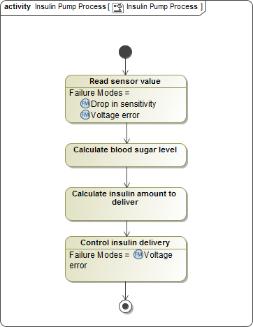
In this Activity Diagram, the Read sensor value and Control insulin delivery Actions are linked to the Drop in sensitivity and Voltage error Failure Modes.
Usability tip
An element can be linked to multiple Failure Modes. You can either select multiple Failure Modes and drag them to the element shape all at once, or drag the Failure Modes one by one. The element shape is then updated and displays all linked Failure Modes.
Linking Failure Modes to elements in the Specification window
Linking a Failure Mode to a model element specifies it as the property value of that element. This link can be defined in the Specification window of the element, as described below.
To link a Failure Mode to an element in the Specification window
- Open the Specification window of the element you want to link.
- In the Properties drop-down box, select the All property display mode, if it is not already selected.
In the property specification area, select the Failure Modes property specification cell, and click
 .
.In the Select Elements dialog, select the Failure Mode(s) you want to link to the element.
Click
 to add the selected Failure Mode(s) to the Selected elements area. If you want to add all Failure Modes contained in a specific Package, select a Package and click
  .
.Removing links
If an an element already has a Failure Mode linked to it, you can use the Select Elements dialog to remove the link:
- In the Selected elements area, select the Failure Mode(s) the link(s) to which you want to remove.
- Click
 . If you want to remove the links to all the Failure Modes shown in the Selected elements area, click
  .
. - Click OK, and close the Specification window.
- Click OK.
- Close the Specification window.
After following the steps described above, the selected Failure Modes are specified as the values of the Failure Modes property of the desired element. In addition, the Failure Modes property is automatically displayed on the element shape if that element is displayed in a diagram.