On this page
You can use MATLAB® to evaluate expressions written in MATLAB syntax in Cameo Simulation Toolkit. You must install MATLAB® first and set up your system to call and use it in Cameo Simulation Toolkit.
Note
- For successful integration, you must use either the 64-bit or 32-bit version of MATLAB (Version 2012a or later) to align it with the 64-bit or 32-bit version of modeling tools, e.g., MagicDraw or Cameo Systems Modeler.
- For Mac users, Cameo Simulation Toolkit version 18.5 SP2 and later can integrate with MATLAB® 2016b seamlessly without disabling System Integrity Protection (SIP) unless it is necessary to disable SIP as a new feature of the latest OS X El Capitan for successful integration.
Warning
MATLAB® 2014a on Mac OS is not capable of evaluating and returning values via the Simulation console, which causes MagicDraw to freeze. To solve this problem, please consider upgrading MATLAB® 2014a to 2014b or later.
Disabling OS X El Capitan's System Integrity Protection (SIP)
To disable OS X El Capitan's System Integrity Protection (SIP)
- Restart your Mac.
- As soon as the screen turns black, hold down the command+R keys to access the Recovery Partition.
- Release the keys once the Apple logo appears on your screen.
- Click the Utilities menu and select Terminal.
- Type
csrutil disableinto the Terminal window and press Return. - The Terminal should display a message that SIP was disabled.
- Restart your Mac for the changes to take effect.
- Run MagicDraw/Cameo System Modeler and integrate it with MATLAB®.
Integrating MagicDraw or Cameo Systems Modeler with MATLAB® (on Microsoft Windows or Mac OS X)
Note
To enable the Integrations menu under the Tools main menu, you must change the perspective to System Engineer or Software Architect by doing the following:
- From the main menu, select Options > Perspectives > Perspectives. The Select Perspective dialog opens.
- Select System Engineer or Software Architect and click Apply. The Integrations menu will be enabled.
To integrate MagicDraw or Cameo Systems Modeler with MATLAB® (on Microsoft Windows or Mac OS X)
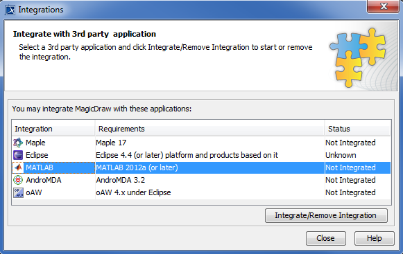
From the main menu, click Tools > Integrations. The Integrations dialog opens.
- Select MATLAB® and click Integrate/Remove Integration. The MATLAB® directory selection dialog opens.
- Specify the directory where you installed MATLAB® and click OK.
Note
- If there are problems with integrating MATLAB® on Windows, please ensure that MagicDraw is running with the administrator's privileges, and then try to integrate again.
- When integrating with MATLAB® for the first time or changing the MATLAB® version, restart your machine.
- If the system has been integrated with MATLAB® previously, you do not have to restart the system since system variables have already been updated. Only restart MagicDraw.
You can also integrate MagicDraw or Cameo Systems Modeler with MATLAB® manually using the following steps.
- Using MATLAB on 32-bit and 64-bit Microsoft Windows
- Using MATLAB on Mac OS 10.6 (Snow Leopard)
- Using MATLAB on 32-bit and 64-bit Linux
Connecting to a running MATLAB session
Simulation Toolkit can make connection to a running MATLAB session, thus all variables in the workspace can be used.
To connect Simulation Toolkit to a running MATLAB session through sharing
- Execute the matlab.engine.shareEngine command through the MATLAB Command window.
Note
- MATLAB must be integrated successfully before the connection is made.
- If the sharing command shown above is not executed, the other MATLAB session loaded by Simulation Toolkit will be used instead of the shared one.
After the session connection, Simulation Toolkit can access variables in the MATLAB shared workspace that are not in the SysML model. You can define some variables in MATLAB, e.g., m1 and m2 and solve parametric in Simulation Toolkit. These two groups of variables are then merged and can be accessed in MATLAB as shown in the following figure.
Variables in the shared MATLAB workspace can be used in either Simulation Toolkit or MATLAB.
Simulink co-simulation
Cameo Simulation Toolkit supports Simulink (MATLAB) co-simulation. Simulation executes the entire Simulink model (*.slx) on all steps, if there are any value changes in the input, which is similar to FMI. Simulation works with Simulink models as attached files and Simulink models located in the same directory of the project.
Warning
- You must successfully integrate MATLAB Version 2016b or later before using Simulink co-simulation. See Integration with MATLAB.
- Any duplicated Simulink model is not allowed in the project.
Note
- Simulink models without input/output Ports are not executed because there is no connectivity, and value change is not propagated to the Block.
- This type of Simulink integration is for atomic calculations. When any input changes, outputs such as the parametric diagram are calculated, e.g. In1 → Gain5 → Out1. It occurs as one step of Simulation time, the same as FMU.
- If the simulink file (.slx) is updated or modified, Simulation needs to restart the MATLAB session by calling the
kill matlabcommand in the Simulation console.
To use Simulink co-simulation
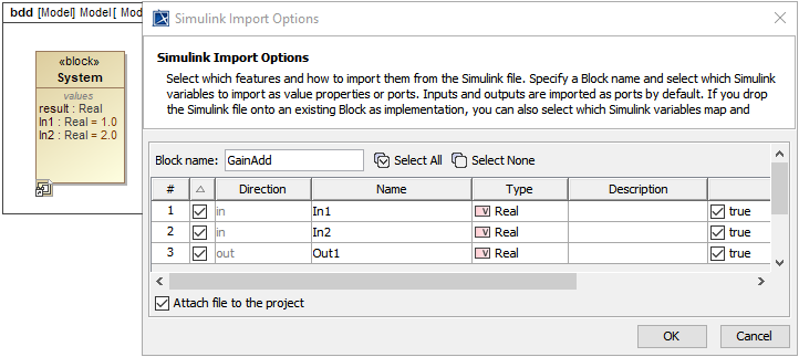
Drag a Simulink model into the Block Definition diagram or Internal Block diagram of the project. The Simulink Import Options dialog will be shown as in the figure below. All input/output Ports are selected by default.
The Simulink Import Options dialog is shown after dragging a Simulink model into the Block Definition diagram or Internal Block diagram of the project.
Note
- You can select the Attach file to the project option to attach the model to be displayed in the Containment tree.
- The model will be shown as «SimulinkBlock» «Block».
- The Block name will be used as the model name.
- Input and output Ports of the Block will be exposed as Flow Ports with directions.
- Connect those Flow ports through binding Connectors in the Internal Block diagram.
- Run the simulation. When inputs are available for initialization (e.g., passed via binding), «SimulinkBlock» will be run at the first time and on every input change. You can also see animation of Flow Ports and set breakpoints for debugging.
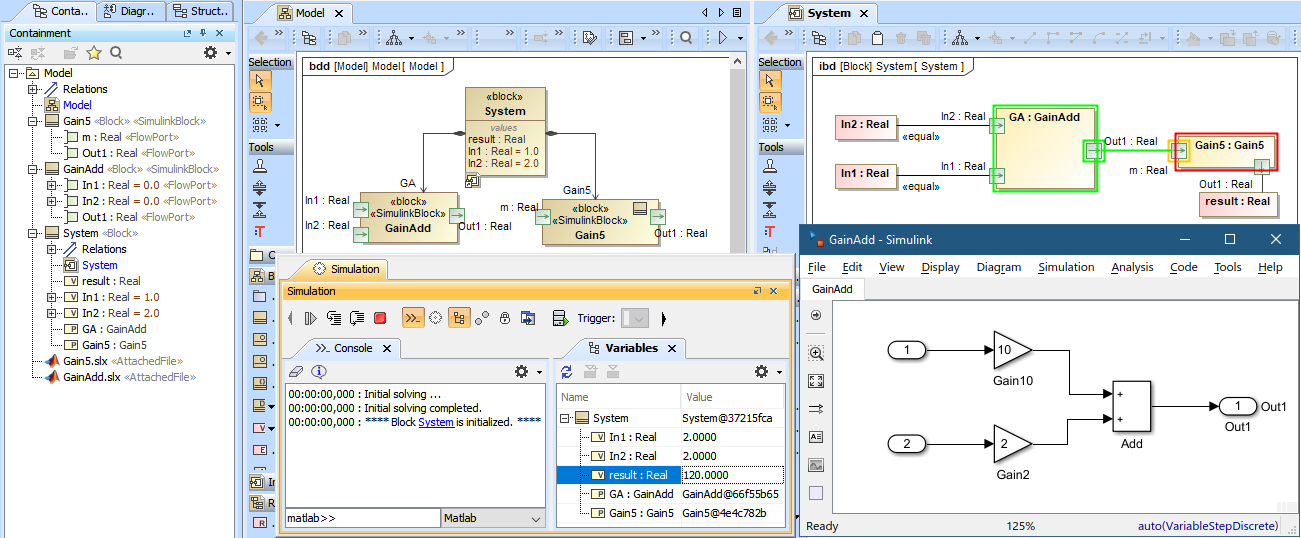
From the figure below, a system is with two Simulink models: GainAdd and Gain5. GainAdd will multiply Port In1 by 10, multiply Port In2 by 2, and add the two results to Port Out1. Gain5 will multiply Port m by 5. Therefore, result will be [(2 * 10) + (2 * 2)] * 5 = 120.


