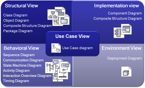
UML defines 13 diagrams that describe 4+1 architectural views:
Several kinds of diagrams provide a visual notation for the concepts in each view.
Use Case view
The use case view represents the functionality and behavior of a system or subsystem as it is perceived by external users. This view is targeted mainly at customers, designers, developers, and testers.
The use case view usually is presented as a number of use cases and actors in Use Case diagrams. Occasionally it is used in Activity and Sequence diagrams.
The use case view is central because the contents drive the development of the other views. It is also used for project planning. Every single use case unit is deemed as a manageable unit during the project execution.
Structural view
The structural view represents structural elements for implementing a solution for defined requirements. It identifies all of the business entities and how these entities are related to each other. Usually entities are represented as classifiers and their instances in Class and Object diagrams in multiple abstraction levels. System decomposition to different layers can be displayed using Package diagrams. A Composite Structure diagram can be used to represent the classifier inner structure. The system structural view artifacts are created by software architects and represent the system implementation design solutions.
Behavioral view
The dynamic behavior of the system is displayed on the Interaction (Sequence and Communication), State, Activity, Interaction Overview, and Time diagrams. It focuses mainly on the interactions that occur between objects inside a system, activities and work performed by the various parts of a system, and state changes within a particular object or collaboration. Rather than defining the participants of the system, it defines how particular use cases are executed, which provides value for the external user. The dynamic view is concerned about what is happening inside the system and how those actions impact other participants.
Implementation view
The implementation view describes the implementation artifacts of logical subsystems defined in the structural view. It can include the intermediate artifacts used in a system construction (code files, libraries, data files, etc.) This view defines dependencies between the implementation components and their connections by the required and provided interfaces. Components and their relationships are displayed on the Component diagram. Inner parts of the component can be represented with the Composite Structure diagrams. The implementation view helps analyze system parts and their dependencies in a higher component level.
Environment view
The environment view represents the physical arrangement of a system, such as computers and devices (nodes) and how they are connected to each other. In contrast to the component view, the deployment view is concerned with the physical structure of the system and the location of the software modules (components) manifested by artifacts within the system.
The environment view is displayed on the Deployment diagram.
