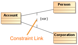
A Constraint Link is a graphical representation of a constraint element. The Constraint Link is shown on the diagram pane as a dashed arrow from one shape to another. You can assign a particular constraint to the Constraint Link. The constraint assigned to the Constraint Link is labeled in braces: {} . See an example of the constraint representation in the following figure.
On the Constraint Link, you can display the constraint direction arrow. The direction of the arrow represents a relevant information within the constraint. The client (the tail of the arrow) is mapped to the first position and the supplier (arrowhead) is mapped to the second position in the constraint.
You can format the constraint symbol properties in the Symbol Properties dialog.
After applying the constraint to the Constraint Link, you can specify the constraint in the Constraint specification window. In the same window, you can find the description of all constraint properties. Descriptions are presented in the description area of the Specification window.
To draw a Constraint Link
- In the Class, Use Case, Sequence, or Activity diagram palette, under the Common category, expand the Constraint command and select the Constraint Link.
- Draw a Constraint Link between desired shapes.
To add a constraint expression to the Constraint Link
- From the Constraint Link shortcut menu, choose the Select Constraint and do one of the following:
- Select Create Constraint to create a new constraint.
- Choose a constraint from the list.
To display a Constraint Link direction arrow
Select the Constraint Link and from the shortcut menu, select Show Arrow.
The direction of the Constraint Link will be displayed. See an example in the following figure.
![]()