A Connector specifies a link that enables communication between two or more instances. This link can be an instance of an association, or it can represent the possibility of the instances being able to communicate because their identities are known by virtue of being passed on as parameters, held in variables or slots, or because the communicating instances are the same instance.
The link can be realized by something as simple as a pointer or by something as complex as a network connection. In contrast to the associations, which specify the links between any instance of the associated classifiers, the connectors specify the links between instances playing the connected parts only.
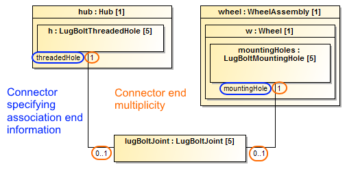
Each connector can be attached to two or more connectable elements, each representing a set of instances.
You can specify connector and connector end properties in the connector and connector end Specification window. In the same window, you can find the description of each property. Descriptions are presented in the description area of the Specification window.
Drawing a connector end
A Connector has at least two ends, each representing the participation of instances of the classifiers typing the connectable elements attached to the end. The set of Connector ends is ordered. The connector end information can be displayed on the diagram.
Selecting a Port automatically when drawing a Connector
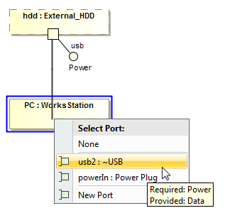
To select a Port automatically when drawing a Connector from a Port to a Part
- Select a Port on the diagram pane.
On the smart manipulator toolbar, click
 and select Part shape. The Select Port menu appears.
The menu appears if a new Port can be created on the Part or the Part has hidden Ports.
- Select one of the following command:
- None - if you want to connect connector straight to the part.
- On a port in the list. Hidden ports of the part are listed. The selected port will be represented on the diagram and the connector will be connected to it.
- New Port - to create a new port with the same name, type and multiplicity as the port from which the connector is drawn.
- New Nested Port - to create a new nested port. Note that the command exists only if the connector is drawn from the nested port.
You can draw a connector to a Port too and the menu appears. As a result, the nested Port is created.
Hiding Connector type
You can hide the type name of the represented Connector on the diagram pane.
To hide the type name of Connector
- Select a single or any number of Connectors on the diagram pane.
- Right-click to open the shortcut menu.
- From the shortcut menu, select Symbol Properties.
- In the Symbol Properties dialog, set the Show Type option value to false.
The name of the Connector type is hidden and no longer visible in the Connector label.