On this page
Prerequisites
- MagicDraw/Gears Bridge is installed on the modeling tool.
- An asset model is defined in the Big Lever Software Gears program.
- A system model (a superset or 150% model) is defined in MagicDraw.
Modeling tool
MagicDraw as a modeling tool is used in descriptions as an example.
Connecting asset and system projects
To connect asset and system models
Note
This procedure is required when starting the project for the first time.
- In Big Lever Software Gears, click Add New Asset, choose the MagicDraw Project or Package type of an asset name, and click OK.
- Open the system project in MagicDraw.
Define the Bridge Asset URI. In MagicDraw, select the root package (the Model) of your system project. On the main menu, click Tools > Gears > Show Project or Package URI. The URI address appears in the Gears Output window. Copy the address and return to the Gears program. Paste the address in the Bridged Asset URI box in the Asset Properties Editor dialog and click OK.
- Set the Gears focus in MagicDraw. Switch to MagicDraw and, on the main menu, click Tools > Gears> Set Gears Focus. In the Set Gears Focus dialog, browse to the Gears project and click Select after you are done.
Specifying the variation points in the system model
In the system model, in a modeling tool, you must specify variation points and define how the feature choices impact the variation point. Variation points can be set on Blocs.
To set variation points
- In the Block Definition Diagram (BDD), select an element (either an element in the Model Browser or a symbol on a diagram pane) for a variation point.
- Open the shortcut menu of the selected element. Click Gears > Convert to Variation Point.
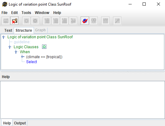
- Provide the variation point logic to define how the feature choices impact this variation point. Select an element declared as a variation point and, in the element's shortcut menu, click Gears > Edit Logic.
- In the open Logic of variation point dialog, create the expression and save it.
- Repeat steps from #2 to #4 for all elements you need to set as variation points.
Generating a particular product variant
After assigning variation points and their logic, you can generate a particular product variant.
To preview a particular product variant realization
- On the main menu, click Tools > Gears > Actuate.
- In the Actuate Gears Product dialog, select one of the defined product configurations and click OK. Model elements not needed for this product configuration have a red line across them. Model elements that are needed are highlighted in yellow.
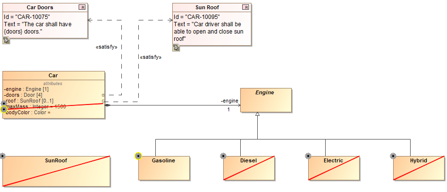
Notation of elements in the model after actuating the project by a defined product configuration.
To generate a particular product variant
- On the main menu, click Tools > Gears > Actuate to Staging Area.
- In the Actuate to Staging Area dialog, select a product to actuate, specify a location to save a product variant, and type a suffix and/or prefix to add to a project name if needed. Click OK after you are done.
Note
You can also generate a particular project variant in the Gears program. In this way, you can cut not only the system model in MagicDraw, but all artifacts connected to the Gears project - requirements, documentation, etc.
Other resources
- Product Line Engineering Meets MBSE — the Best of Both Worlds. A record of the webinar.