On this page
Introduction
The extract structure feature allows you to select a portion of an existing system structure and transform it into another reusable Block (or Subsystem) which may then be used as parts in many other structures. You can also play a 'move' or a 'decompose' role when a structure becomes too complex and requires to be decomposed into several smaller reusable parts. Recursive decomposition of structure and behavior is an important aspect of the iterative development process. This feature is particularly useful for the automotive, aerospace, and defense communities for modeling complex systems-of-systems and building reusable components.
You can extract your structure by using the Extract Structure Wizard. It allows you to extract selected Part Properties of an Internal Block Diagram to a separate diagram. Using this wizard, you can:
- Create and specify the target diagram that you want to create as the result of the extraction. The selected part is extracted to the newly created diagram.
- Select the ports that you want to create in a new diagram. Ports are listed for each intersected connector from the source diagram.
- Specify a referencing element (in this case, a property) that is created in the source Internal Block Diagram and represents the elements moved to the target diagram during the extraction.
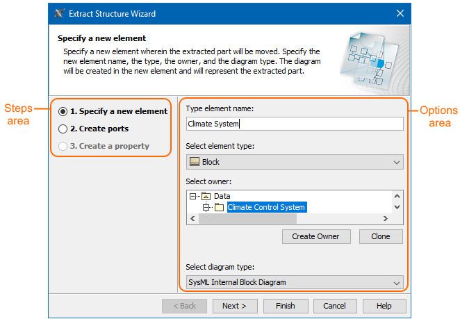
The Extract Structure Wizard areas
The Extract Structure Wizard consists of the following areas:
- Steps area: displays all steps of the wizard and shows the current step you are working on.
- Options area: allows you to select and specify required options.
Using the Extract Structure Wizard
To extract structure
- In the SysML Internal Block Diagram or a structure compartment, select Part Properties that you want to extract.
- Right-click selected parts and from the shortcut menu select Refactor > Extract.
- Follow the steps of the Extract Structure Wizard. How to work in each step of the Extract Structure Wizard >>
- Click Finish when you are done.
Selected Part Properties are decomposed: another reusable Block (or Subsystem) and Internal Block Diagram are created (see the figure below).
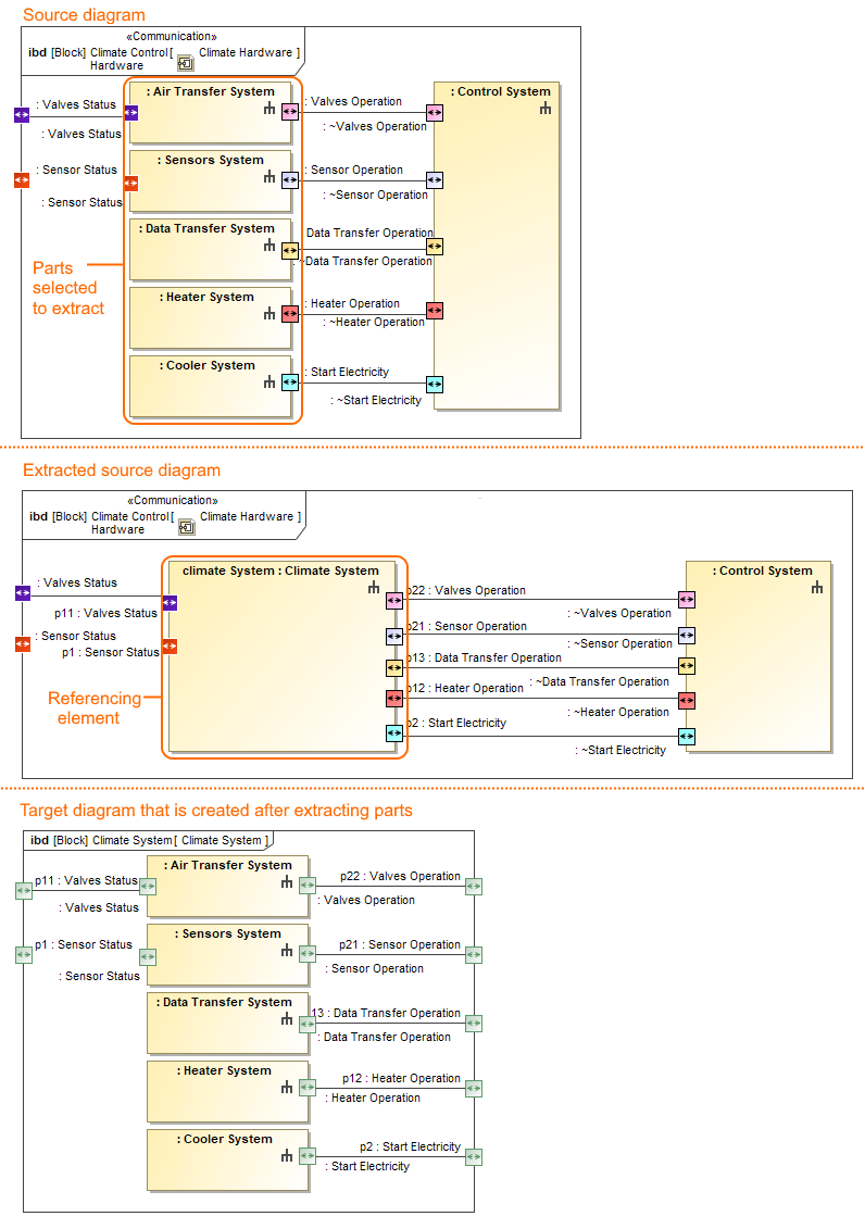
The selected Part Properties in the Climate Control IBD are extracted. As a result the new climate System Block and the SysML Internal Block Diagram are created.
Sample model
The model used in the figures of this page is the climate control system sample model. To open this sample do one of the following:
- Download climate control system.mdzip.
- Find in modeling tool <modeling tool installation directory>\samples\SysML\climate control system.mdzip.