To generate a Simulink model directly from the modeling tool
Right-click the Block TestCaseSignalProcessor::TestBed and select Tools > Export to Simulink. Please see Generating a simulation file for more information.
Set the options listed below and click OK:
Format: XML (.sdl)
S-Function or Simscape: S-Function version 2
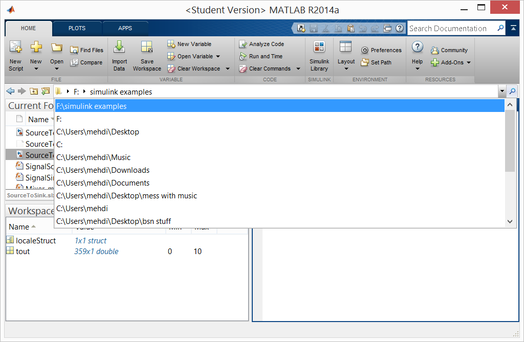
Launch Matlab with Simulink and Simscape extensions.
In Matlab’s Current Directory navigation bar, search for the file directory where the Simulink files (as well as the SysML files) are saved, and set it as the current directory. The Current Folder panel should display the generated .slx and M-files.
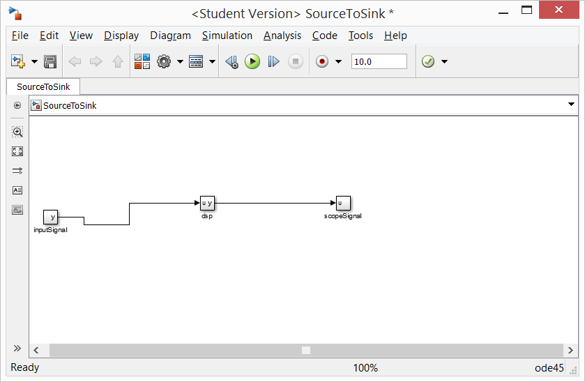
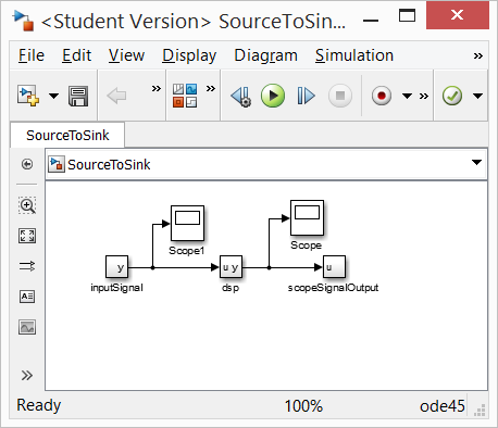
In the Current Folder panel, double-click on the file named SourceToSink.slx. The SourceToSink model will open up in a new Simulink window. Rearrange the blocks to reflect the signal flow arrowheads.
Open the Library Browser either by using the 4-block icon or by going to Tools > Library Browser. Find and click on Sinks among the list in the Libraries panel, which will be categorized under Simulink.
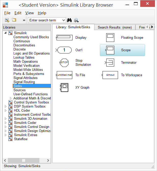
Pull-and-drag the Scope block from the Sinks library list into the SourceToSink Simulink model. Attach a signal line segment from the Scope port onto the signal line that connects the dsp block and the scopeSignal block. Repeat Steps 6 & 7 to add a Scope block and attach it to the signal line segment that connects the inputSignal block to the dsp block.
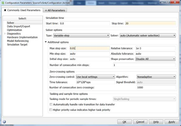
Go to Simulation > Model Configuration Settings. This allows selecting the types of solver and the runtime of the simulation. Select a Start Time of 0, and a Stop Time of 20 (or any other reasonable number of seconds). Under Solver Options, change the solver Type to Variable-step (or any other desirable solver that is suitable). Set the Max step size to 0.01. Press Apply, then press OK.
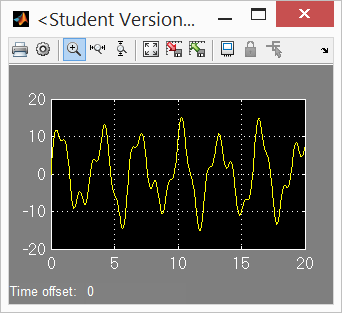
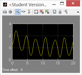
Go to Simulation > Run. Double-click on the Scope block to see the simulation results.