On this page
Introduction
This page describes each step of the Automatic Instantiation wizard in detail. If you are satisfied with the default values provided in the Automatic Instantiation wizard, you can finish the wizard in the first step without making any changes. The instances will be created with the default values and in your working package. If you want to change the default values of a single instance or create multiple sets of instances, follow all steps of the Automatic Instantiation wizard. You can add each set in a different package, as well as display them on the newly created diagrams.
After finishing the wizard, you can create a very large number of instance specifications, depending on the size of your system. That is why we strongly recommend selecting a new package to store all created instance specifications.
Opening the Automatic Instantiation wizard
To open the Automatic Instantiation wizard
- Select the Block for which you want to create instances.
- From the shortcut menu, select Tools > Create Instance.
The Automatic Instantiation wizard opens.
The Automatic Instantiation wizard steps
The Automatic Instantiation wizard consists of three steps:
Step #1. Select parts to be instantiated
In this step, you can see all the available instance specification values (parts) of your selected element. At this point, you can select which parts or properties to instantiate, create or select values for parts and properties, as well as add or remove parallel parts.
You can select/deselect the parts by clicking the check marks next to the parts or the options in the Selection area.
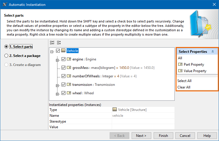
Parts are displayed if the multiplicity is greater than 1. The number of parts displayed depends on the multiplicity.
- The number of parts displayed will equal the multiplicity. For example, if the multiplicity is 2, you will see 2 parts displayed in the Automatic Instantiation wizard. Also, in this case, you will not be able to add parallel parts or remove existing parallel parts.
- If the multiplicity is defined as an interval (for example, 0..*, 1..10, 1..* ) or *, only one part will be created by default. If you need more parts, you can create them by pressing Insert or selecting Add parallel part from the selected property’s shortcut menu.
- If the multiplicity is 1, parts will not be created.
The parts and properties are displayed with the suggested types, names, and values. In this step of the wizard, you can change them.
Selecting a value for an instance
To select a value for an instance
- Select a part to be instantiated to which you want to add a value.
- In Instantiated properties, click a Value specification cell and then click the ... button.
- The Select Instance Specification dialog opens.
- In the opened dialog, select the instance specification you want to add for the selected instance.
- Click the OK button.
To create a value for an instance
- Select a part to be instantiated for which you want to create a value.
- In the Instantiated properties area, click the Value specification cell and then click the Show Shortcut Menu button.

- In the opened shortcut menu, point to the Value Specification and then select one of the available value types.
- In the Value cell, type the desired value.

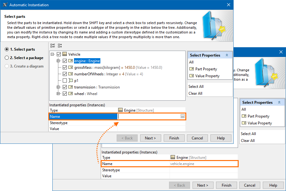
Changing the name of an instance
Each instance has a default name that uses the dot notation. However, you can change the default name by clicking the value row next to the Name property and typing the new name for the instance.
Applying a custom stereotype to an instance
You can also apply the custom stereotype to the instance. Only those stereotypes can be applied that have Instance Specification as their metaclass and whose customizations have a meta property named classifier with the New Types property value set to the instantiated element’s type.
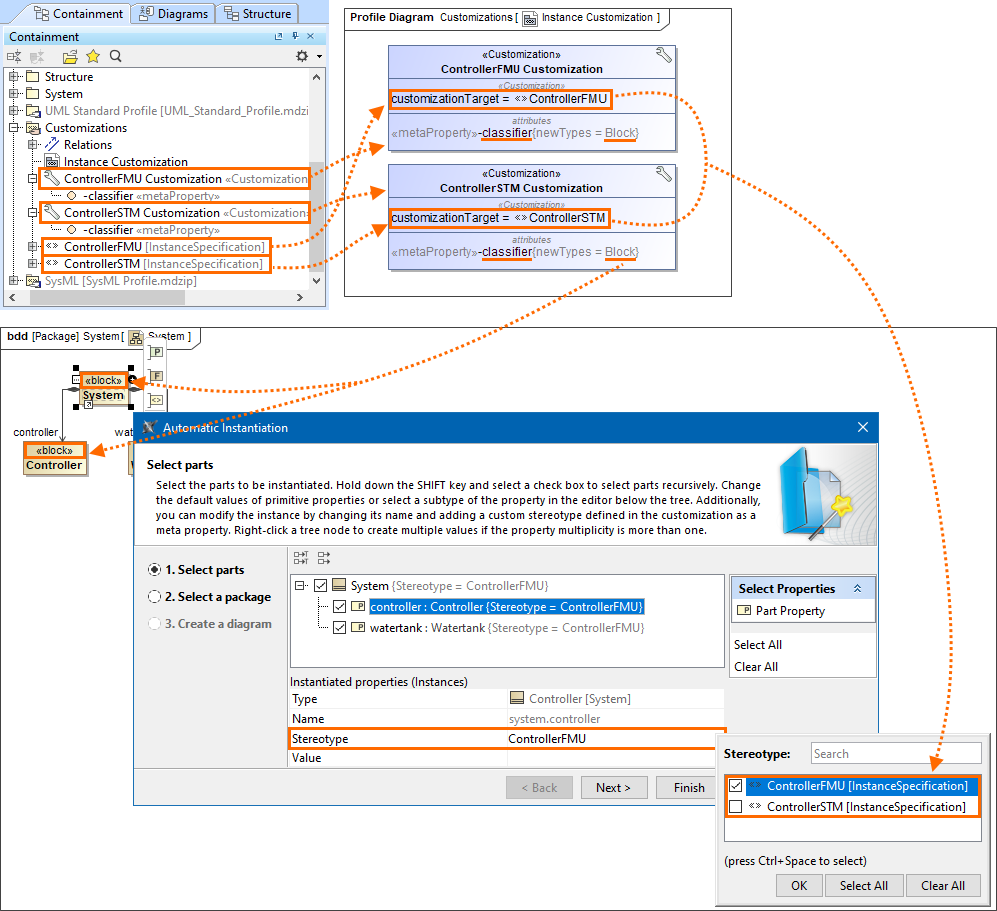
The custom «ControllerFMU» and «ControllerSTM» stereotypes have Instance Specification as their metaclass
and their respective customizations ControllerFMU Customization and ControllerSTM Customization have a meta property named classifier with the New Types property value set to the «Block» stereotype.
Since the Controller block has the «Block» stereotype applied, the «ControllerFMU» and «ControllerSTM» stereotypes can be applied to the Controller block's instance.
Changing a type for an instance
You can change the type for the Part Property instance only if that type is a subtype of a Block (connected through Generalization). As shown in the following figure, the Engine GM Block and Engine GMR Block are subtypes of the Engine Block. When creating an instance for the Vehicle Block, you can change the type of the engine Part Property by selecting one of the following: Engine GM Block, Engine GMR Block, or Engine Block.

Changing the type for a Part Property instance directly in the Automatic Instantiation dialog.
Step #2. Select a package
In this step, you can select the package to store instance specifications. You can select an existing package from the element tree, create a new package, or clone selected packages. Click the Finish button after this step if you do not want to display your created instance specifications.

To create a new Package in the element tree
- In the element tree, select the Package for which you want to create the new one.
- Click the Creation Mode button.
- Click the Create Owner button.
- From the open menu, select the package kind. The Specification window of that package opens.
- Type its name.
- Click Close.
To clone the Packages in the element tree
In the element tree, select the Package to clone.
The Package is cloned recursively including all nested structures.- Click the Clone button.
- The Specification window of cloned Package opens.
- Type its name.
- Click Close.
Step #3. Create a diagram (optional)
In this step, you can choose whether or not to show your created instance specifications in a new diagram. If you do not wish to create a new diagram, you can simply skip this step by clearing the Create a new diagram check box.

To display instance specifications in the new diagram
- Make sure the Create a new diagram check box is selected.
- (Optional) If you want to create and display links between your instance specification(s), select the Create link between instances check box.
Fill in the Type diagram name field by typing the diagram name.
Note
By default, the diagram name is the selected Package's name in Step 2.
- From the Select diagram type drop-down list, select one of the diagram types.
- Specify the owner for a new diagram:
- Select existing Packages from the tree.
- Click the Create Owner button to create a new one.
- Click the Clone button to clone existing Packages.
- Click Finish.
Example
For an example of how to create instances of Blocks with complex structures, see Automatic Instantiation wizard.
Sample model
The model used in the figures of this page is the VehicleStructure sample model. To open this sample, download VehicleStructure.mdzip.